Hardware description
4.8.1 Programming an external board
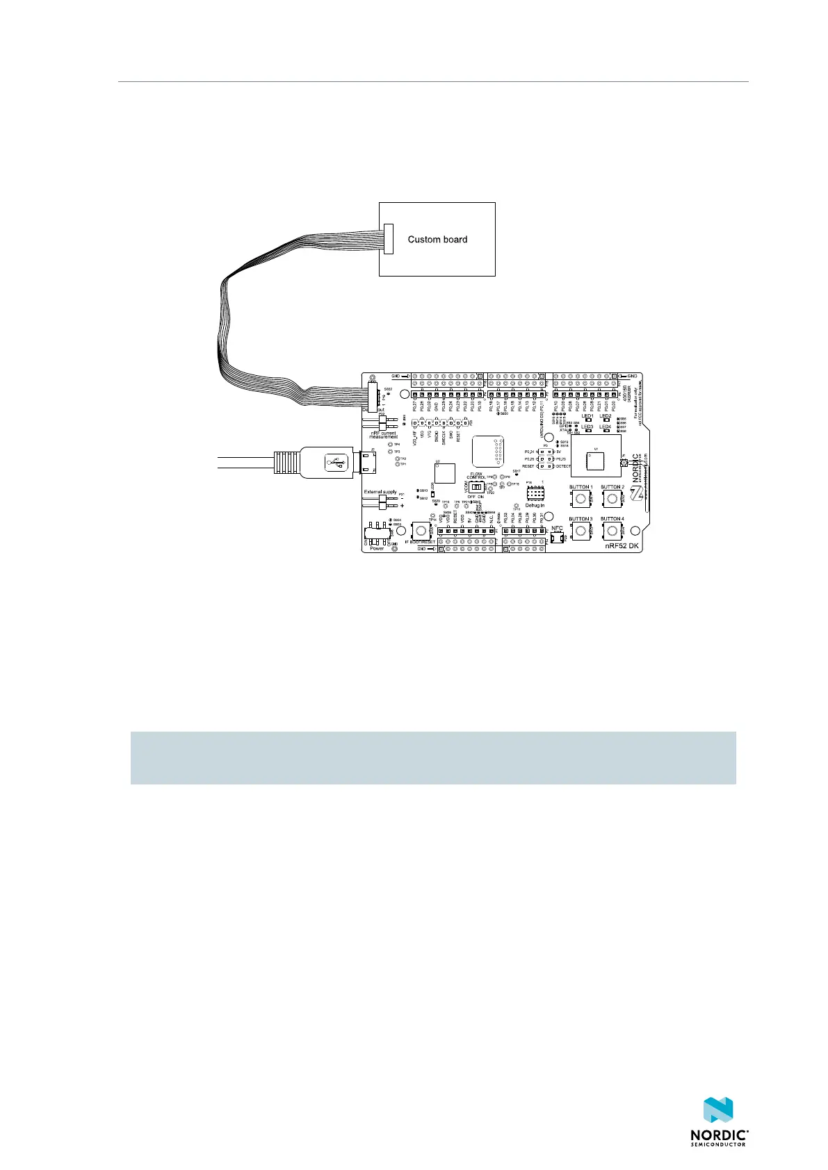
If your custom board has a standard 10-pin Serial Wire Debug (SWD) connector or a connector supporting
a standard 10-pin flat cable, connection to P19 is recommended.
Connect the boards as shown in the following figure.
Figure 20: Connecting an external board to P19
It is recommended to power the external board separately from the DK. The voltage on the external board
must match that of the DK, which is 3.0 V when the DK is powered through the USB connector.
When pin 3 (SWD0_SELECT) of P19 is connected to GND through the 10-pin flat cable, the interface
MCU programs or debugs the target chip on the external board instead of the onboard nRF52832 SoC.
If it is inconvenient to have a separate power supply on the external board, the nRF52 DK can supply
power through the Debug out connector P19. To enable this, short solder bridge SB32.
CAUTION: To avoid damaging your board, do not connect a separate power supply to the external
board when SB32 is shorted.
The following section includes an illustration of the P19 connector pinout with a description table.
4397_500
22