Hardware description
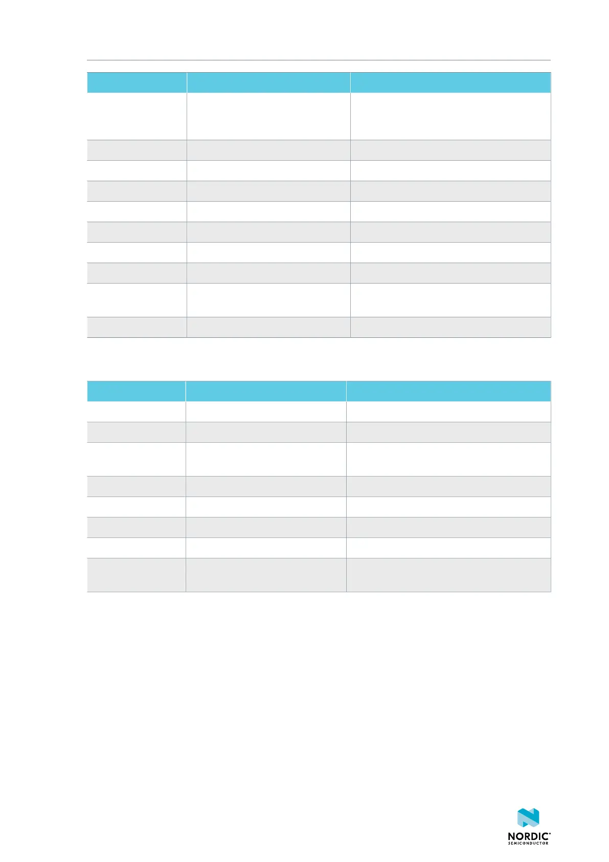
Pin number Signal Description
1 EXT_VTG Voltage supply from the external target,
used as voltage detect input to the interface
MCU
2 EXT_SWDIO Serial Wire Debug (SWD) data line
3 GND Ground
4 EXT_SWDCLK SWD clock line
5 GND Ground
6 EXT_SWO Serial Wire Output (SWO) line
7 N.C. Not used
8 N.C. Not used
9 EXT_GND_DETECT Ground detect. Should be connected to
ground on the external board
10 EXT_RESET Reset
Table 6: Pinout of connector P19 for programming external targets
Pin number Signal Description
1 VDD_nRF Used for current measurement
2 VDD_nRF’ Used for current measurement
3 SH_VTG Voltage supply from the external target, used
as voltage detect input to the interface MCU
4 SH_SWDIO Serial Wire Debug (SWD) data line
5 SH_SWDCLK SWD clock line
6 SH_SWO Serial Wire Output (SWO) line
7 SH_RESET Reset line
8 SH_GND_DETECT Ground detect. Should be connected to
ground on the external board
Table 7: Pinout of connector P20 for programming target on shields
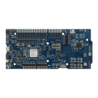
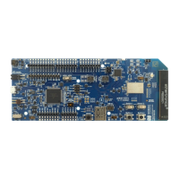
4.10 NFC antenna interface
The nRF52 DK supports an NFC tag.
NFC-A Listen Mode operation is supported on the nRF52832 SoC. The NFC antenna input is available on
connector P23 on the nRF52 DK.
4397_500
20