Hardware description
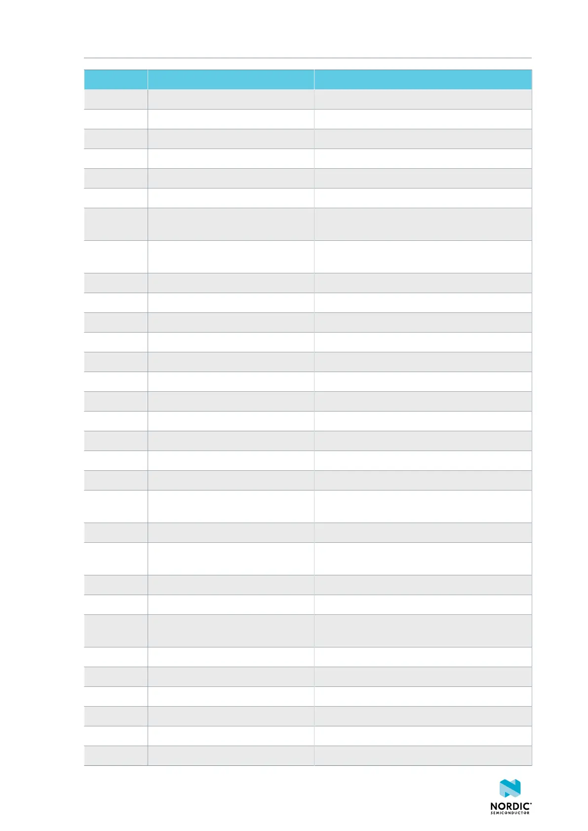
I/O Label Description
P0.03 BUTTON2/NFC2 Button 2 / NFC antenna (Not used)
P0.04 BUTTON3 Button 3
P0.05 BUTTON5 Button 5
P0.06 BUTTON4 Button 4
P0.07 RGB1_LED_RED Red color of the RGB LED 1
P0.08 SPI_SCK SPI clock to hardware codec and microSD card
P0.09 SPI_MOSI SPI data output to hardware codec and microSD
card
P0.10 SPI_MISO SPI data input from hardware codec and microSD
card
P0.11 MICRO_SD_CS SPI chip select signal for microSD card
P0.12 HW_CODEC_MCLK Master clock of hardware codec
P0.13 HW_CODEC_DIN Audio serial port data input of hardware codec
P0.14 HW_CODEC_BCLK Audio serial port bit clock of hardware codec
P0.15 HW_CODEC_DOUT Audio serial port data output of hardware codec
P0.16 HW_CODEC_FSYNC Audio serial port frame sync of hardware codec
P0.17 HW_CODEC_CS SPI chip select signal for hardware codec
P0.18 HW_CODEC_RESET Digital reset input of hardware codec
P0.19 HW_CODEC_IQR Interrupt request (IRQ) output of hardware codec
P0.20 HW_CODEC_GPIO Interrupt request (IRQ) output of hardware codec
P0.21 HW_CODEC_SELECT Interrupt request (IRQ) output of hardware codec
P0.22 SPI_SELECT Input from FTDI chip when FTDI has taken control
of the hardware codec SPI lines
P0.23 PMIC_ISET Current limit set pin for the nPM1100 PMIC
P0.24 BOARD_ID_EN Enable signal for the resistor voltage divider for
version identification
P0.25 RGB_LED1_GREEN Green color of the RGB LED 1
P0.26 RGB_LED1_BLUE Blue color of the RGB LED 1
P0.27 BOARD_ID Enable signal for the resistor voltage divider for
version identification
P0.28 RGB_LED2_RED Red color of the RGB LED 2
P0.29 RGB_LED2_GREEN Green color of the RGB LED 2
P0.30 RGB_LED2_BLUE Blue color of the RGB LED 2
P0.31 LED1 LED 1 (Blue)
P1.00 LED2 LED 2 (Green)
P1.01 LED3 LED 3 (Green)
4406_708
11
 Loading...