3
Hardware description
This section focuses on the hardware components of the nRF5340 Audio DK, with descriptions of the
various hardware components that are present on the device.
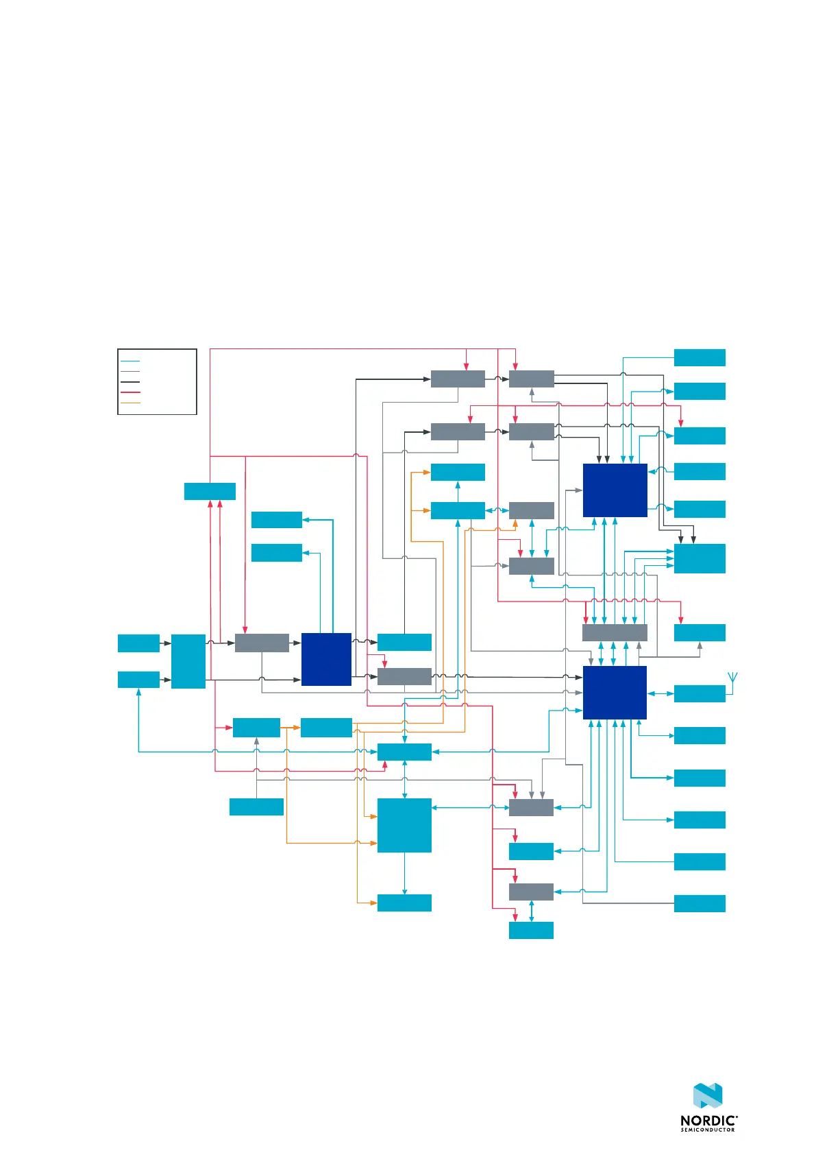
3.1 Block diagram
The block diagram illustrates the nRF5340 Audio DK functional architecture.
Charge LED
Error LED
SD Card
Buttons
Digital Mic
Line In
Headphone
Out
Level
translator
LEDs
GPIO
connectors
External HW
CODEC
interface
SWD
connector
Trace
connector
AUX
interface
Debug
enable switch
Interface
MCU
Analog
switches
USB HUB
Current
measurement
BUCK
regulator
LDO
regulator
LED
Reset
Button
LED
LED
Level
translator
Current
measurement
Current
measurement
RF
connector
LED
Load
switch
Load
switch
nRF5340
Analog
switch
Analog switches
HW CODEC
Load
switch
BUCK
regulator
Battery
connector
USB
connector
Power
switch
Current
measurement
nPM1100
FTDI
Data signal
Control signal
Main power
Auxiliary power
Debug power
Figure 2: nRF5340 Audio DK block diagram
3.2 Hardware figures
The hardware figures show the elements of the nRF5340 Audio DK.
4406_708
8