Hardware description
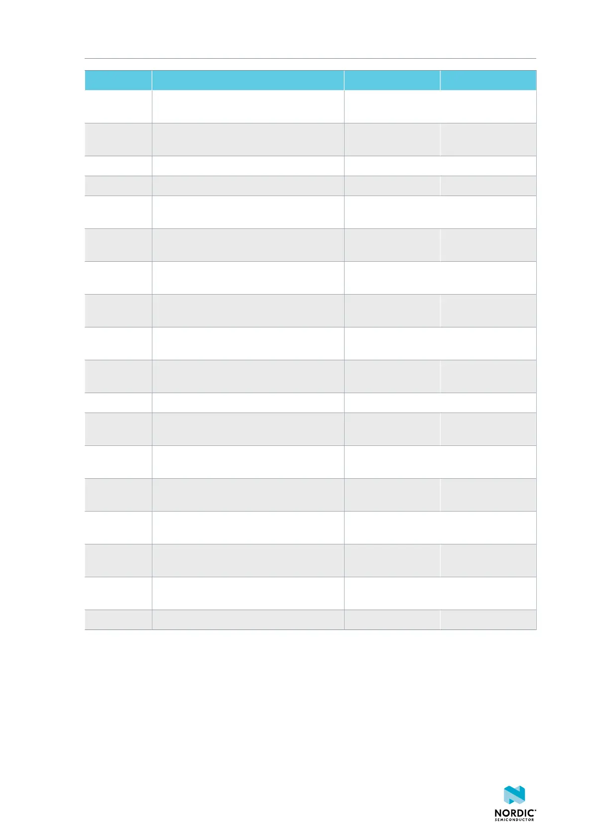
Designator Description Default state Layer
SB7 Cut to enable HW CODEC 1.8V current
measurements on P8
Shorted Top
SB8 Cut to enable VDD_nRF current
measurements on P9
Shorted Top
SB9 Cut to disconnect filter from OUTP Shorted Top
SB10 Cut to disconnect filter from OUTN Shorted Top
SB11 Cut to disconnect the LED for the HW
CODEC GPIO
Shorted Top
SB12 Cut to disconnect digital microphone
POWER from the HW CODEC
Shorted Bottom
SB13 Cut to disconnect digital microphone DATA
from the HW CODEC
Shorted Bottom
SB14 Cut to disconnect digital microphone
CLOCK from the HW CODEC
Shorted Bottom
SB15 Short to connect AUX I2S MCLK to HW
CODEC MCLK1
Open Top
SB16 Short to connect AUX I2S MCLK to HW
CODEC MCLK2
Open Top
SB17 Short to connect P5 pin 6 to GND Open Top
SB18 Cut to disconnect P5 pin 6 from SHIELD
DETECT
Shorted Top
SB19 Cut to disconnect RTS and CTS flow control
lines on UART1
Shorted Top
SB20 Cut to disconnect RTS and CTS flow control
lines on UART2
Shorted Top
SB21 Cut to disconnect nRF53 RESET from RESET
button when debug is disabled
Shorted Top
SB22 Short to permanently connect RESET
button to nRF53 RESET
Open Top
SB23 Cut to disconnect RESET button from
interface MCU
Shorted Top
SB24 Short to bypass analog switch for MCLK Open Top
Table 5: Solder bridges
3.11 Hardware limitations
Different versions of the DK have some hardware limitations and workarounds.
4406_708
19