Hardware description
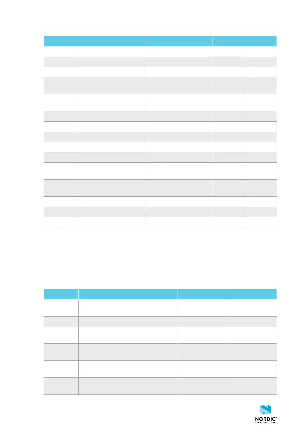
Designator Net Description Size Layer
TP55 NetSB14-1 IN1_PDMCLK pin of CS47L6 1.0 mm Top
TP56 PMIC_ERR nPM1100 error indication 1.0 mm Top
TP57 PMIC_CHG nPM1100 charge indication 1.0 mm Top
TP58 P0.29 RGB LED 2 Green color input
pin
1.0 mm Top
TP59 P0.30 RGB LED 2 Blue color input
pin
1.0 mm Top
TP60 P1.04 UART1 RXD 1.0 mm Top
TP61 P1.05 UART1 TXD 1.0 mm Top
TP62 P1.06 UART1 CTS 1.0 mm Top
TP63 P1.07 UART1 RTS 1.0 mm Top
TP64 NetJ5-10 SD card slot card detect 1.0 mm Top
TP65 P0.11 SD card slot level translator
enable
1.0 mm Top
TP66 P1.15 Current shunt monitor alert
signal
1.0 mm Top
TP67 GND Ground 1.5 mm Top
TP68 LINE_IN.LEFT Line-in jack tip 1.5 mm Top
TP69 LINE_IN.RIGHT Line-in jack ring 1.5 mm Top
Table 4: Test points
3.10.2 Solder bridge overview
The nRF5340 Audio DK has a range of solder bridges for enabling or disabling selected functionalities.
Changes to the solder bridges are not needed for normal use of the DK.
The following table is a complete overview of the solder bridges on the nRF5340 Audio DK.
Designator Description Default state Layer
SB1 Short to connect digital microphone DOUT
to P1.06
Open Top
SB2 Cut to disconnect P0.12 from TRACE Shorted Top
SB3 Short to connect PMIC MODE to VOUTB,
must not be shorted while SB4 is shorted
Open Top
SB4 Cut to disable PMIC MODE from GND, must
not be shorted while SB3 is shorted
Shorted Top
SB5 Cut to enable VBAT current measurements
on P6
Shorted Top
SB6 Cut to enable HW CODEC 1.2V current
measurements on P7
Shorted Top
4406_708
18