Hardware description
3.10 Interfaces
The nRF5340 Audio DK has points for test purposes and solder bridges for enabling and disabling different
functionalities.
3.10.1 Test points
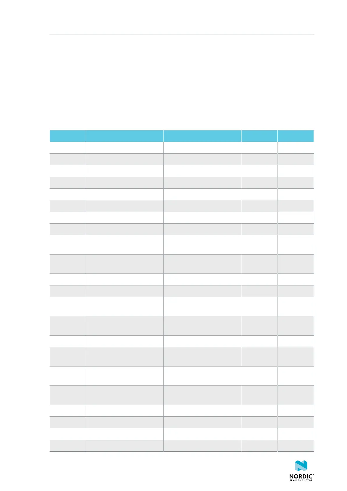
The nRF5340 Audio DK has several test points that can be useful during development and debugging.
The following table is a complete overview of the test points.
Designator Net Description Size Layer
TP1 NetTP1-1 IN1LP_1 pin of CS47L63 1.5 mm Bottom
TP2 NetTP2-1 IN1LN_1 pin of CS47L63 1.5 mm Bottom
TP3 NetTP3-1 IN1RP pin of CS47L63 1.5 mm Bottom
TP4 NetTP4-1 IN1RN pin of CS47L63 1.5 mm Bottom
TP5 NetTP5-1 IN2LN pin of CS47L63 1.5 mm Bottom
TP6 NetTP6-1 IN2RN pin of CS47L63 1.5 mm Bottom
TP7 HW_CODEC_AUX_I2C.SCL AUX SCL pin of CS47L63 1.5 mm Top
TP8 HW_CODEC_AUX_I2C.SDA AUX SDA pin of CS47L63 1.5 mm Top
TP9 P0.07/AIN3 RGB LED 1 Red color input
pin
1.5 mm Top
TP10 P0.28/AIN7 RGB LED 2 Red color input
pin
1.5 mm Top
TP11 P1.01 LED 3 input pin 1.5 mm Top
TP12 P0.04/AIN0 Button 3 1.5 mm Top
TP13 VDD_EXT_HW_CODEC.1V2 External HW CODEC 1.2 V
supply
1.5 mm Top
TP14 VDD_EXT_HW_CODEC.1V8 External HW CODEC 1.8 V
supply
1.5 mm Top
TP15 BAT_NTC Li-Po battery NTC pin 1.5 mm Top
TP16 BATTERY Li-Po battery voltage after
power switch
1.5 mm Top
TP17 NetC41-1 USB voltage after power
switch
1.5 mm Top
TP18 NetC43-2 USB voltage before power
switch
1.5 mm Top
TP19 HEADPHONE.OUTP Headphone jack tip 1.5 mm Top
TP20 HEADPHONE.OUTN Headphone jack sleeve 1.5 mm Top
TP21 DU_N USB connector D- 1.5 mm Top
TP22 DU_P USB connector D+ 1.5 mm Top
4406_708
16