Hardware description
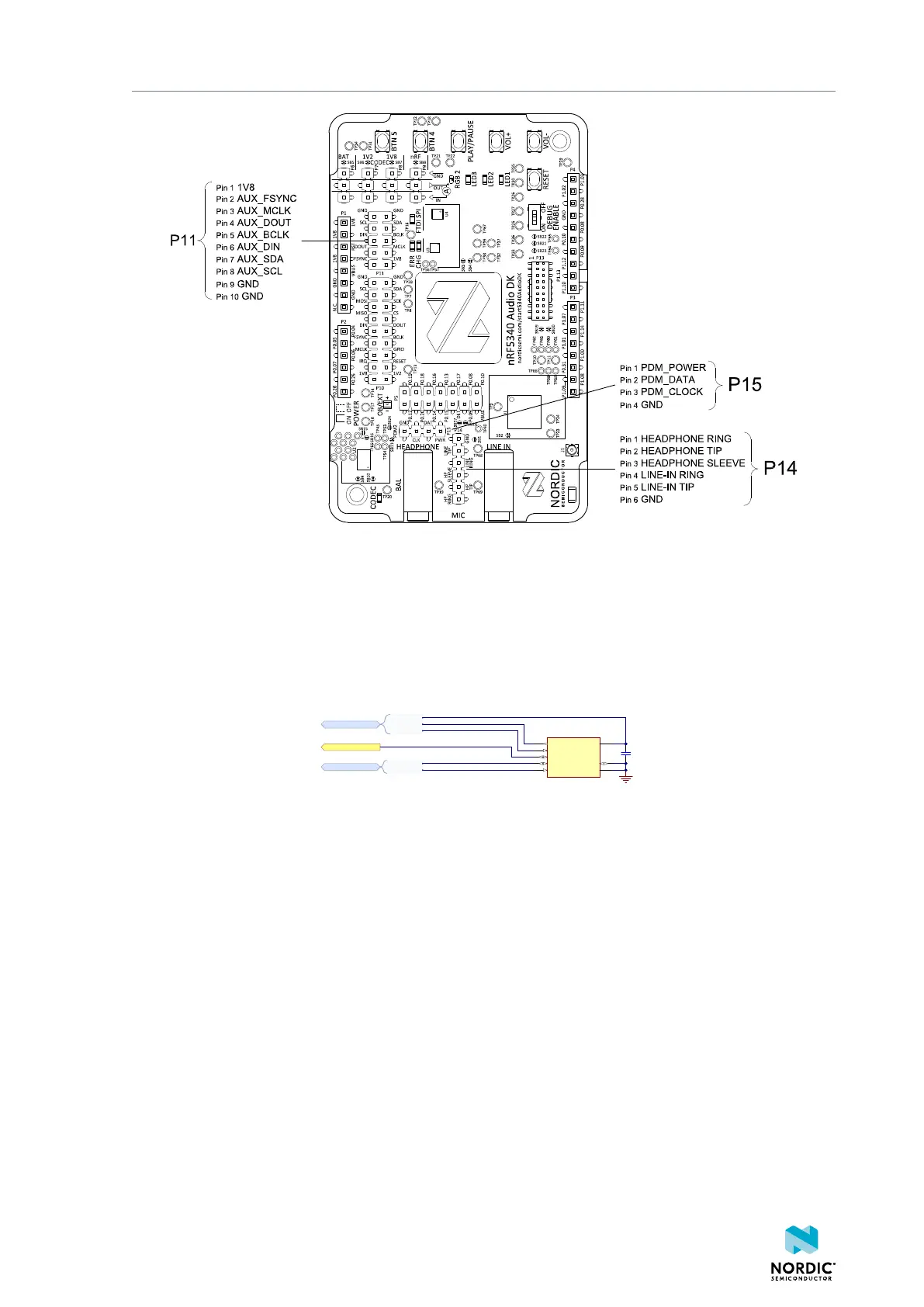
Figure 10: Interface connectors for onboard hardware codec
3.7 Microphone
The PDM microphone (U5) on the nRF5340 Audio DK captures audio input.
The following schematic describes the PDM microphone.
CLK
5
DATA
1
SDA
2
SCL
4
VDD
6
L/R SEL
7
GND
8
DOUT
3
U5
VM3011
C40
100nF
I2C address: 0x60
MIC_PDM
CLOCK
DATA
POWER
PDM
SCL
SDA
I2C
MIC_I2C
MIC_DOUT
Figure 11: PDM microphone
3.8 LEDs and buttons
The user interface on the nRF5340 Audio DK consists of five user-programmable LEDs and five user-
programmable buttons.
The two buttons (SW1) and (SW1) are the VOL- and VOL+ buttons, respectively. Button (SW3) is for PLAY/
PAUSE.
The following schematic describes the LEDs and buttons.
4406_708
14



 To Next Page