4. lnstalla tion
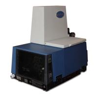
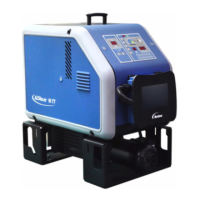
General requirements l Install the applicator so panels can be removed and the unit is
othewise accessible for operation. See Figure 3.2 for required
clearances.
6.L 2
T
(216 mr;\)
1_
0
0
3 (&yl%)
I
(&yIrIr, J
lS.6 In. 4
(351 mm)
1.6 In.
-(41 mm)
r
2 inches
(51 mm)
J
Ygure 3.3 - Applicator Overhang
Dimensions
Figure 3.2 - Applicator Clearance
Dimensions
7 Clearance for opening door panel
2 Clearance for filter removal
3 Clearance for pump enclosure removal
4 Clearance for electrical enclosure
removal
5 Top of applicator motor cover to bottom
of foot pad spacing
6 Top of tank cover to bottom of foot pad
spacing
l Make sure that the applicator overhangs its support platform by
about 2 inches (5 cm.) so that the unit will not drain onto the platform
(see Figure 3.3).
l Avoid unusual ambient temperature conditions, such as below 32°F
(0°C) or above 120°F (50°C).
l Protect the applicator from unusual dust conditions and severe
vibration.
l If the applicator is installed in a drafty area, shield the guns from the
draft. Rapid heat dissipation due to air movement across the guns
can prevent the guns from operating properly.
l The applicator is not designed for water-washdown environments.
A
‘r
WARNING: Risk of electrical shock. Spraying water on the
Series 2300 Applicator may cause water to enter the unit,
resulting in an electrical shock hazard.
l Ensure that the applicator is level to prevent the tank from
overflowing.
P/N 106 701A
41-2300SP - Issued I,94
0 Nordson Corporation 1994
All Rights Reserved

 Loading...


