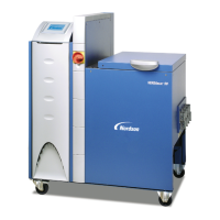
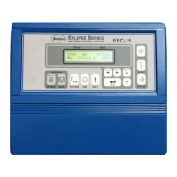
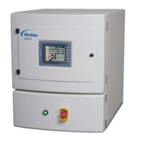
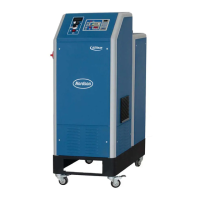
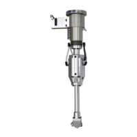
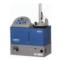
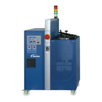
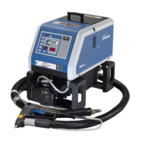
Melter configuration
PUMP 1 PUMP 2 PUMP 3 PUMP 4
Pressure
build-up
function
Pressure
build-up
function
Pressure
build-up
function
Pressure
build-up
function
Analog pressure
sensor setup
Pressure sensors
New sensor
Pressure sensors
New sensor
P SENSOR A1
P SENSOR B1
P SENSOR A2
P SENSOR B2
Operation
4-59
P/N 7105144G
2008 Nordson Corporation
VersaBlue_NW
Select Pressure Build-up or Pressure Control
The mode in which it should operate can be selected for each pump here.
The parameters are set in in the motor screens.
Depending on what is selected in this screen, speed control / pressure
control or speed control / pressure build-up feature can be selected in the
motor screen M5.
Fig. 4-75 V28
Pressure Sensor Setup
A CAN bus sensor is found automatically and indicated by the lamp.
Continue with
to assign the pressure sensor to a pump (example).
NOTE: Only one
pressure sensor can be assigned at a time.
Fig. 4-76 V22
The first two lines are intended for two pressure sensors of pump 1, lines 3
and 4 for two pressure sensors of pump 2.
Indication lamp lit: The pressure sensor is assigned.
NOTE: Pressure sensor A is usually located at the melter outlet, behind the
filter cartridge (default). With the option Pressure display and pressure
control, it transmits the values to the motor controller.
Fig. 4-77 V23

 Loading...
