10
6. Allow the unit to remain under vacuum for at least 30
min.
7. Weigh-In the proper amount of new (or reclaimed) R-22
refrigerant. Refer to Table 3 or the units rating label to
determine the correct amount of charge.
• Refrigerant charging charts are applicable only to
matched assemblies of NORDYNE equipment and
listed airfl ows for the indoor coil. Refer to Figures 6 -
12 (pages 11 - 14) and Tables 4 - 10 (pages 15 - 18)
for correct system charging.
• JT5BD outdoor units with indoor coils not listed are
not recommended. Deviations from rated airfl ows or
non-listed combinations may require modifi cation to the
expansion device and refrigerant charging procedures
for proper and effi cient system operation.
• The refrigerant charge can be checked and adjusted
through the service ports provided external to the
outdoor unit. Use only gage line sets which have a
“Schrader” depression device present to actuate the
valve.
Charging an R-22 system in AC mode at outdoor tem-
peratures above 55° F for optimized sub-cooling of 10°
F - 12° F.
1. With the system operating at steady-state, measure
the liquid refrigerant pressure (in psig) at the outdoor
unit service valve.
2. Measure the liquid refrigerant temperature (in
Fahrenheit) at the service valve.
3. Determine the required liquid refrigerant pressure. Refer
to Tables 11 - 17 (pages 19 - 22) for correct system
charging.
• If the pressure measured in Step 1 is greater than
the required liquid refrigerant pressure determined in
Step 3, then there is too much charge in the system.
Remove refrigerant and repeat Steps 1 through 3
until the system is correctly charged.
• If the pressure measured in Step 1 is less than the
required liquid refrigerant pressure determined in
Step 3, there is too little charge in the system. Add
refrigerant and repeat Steps 1 through 3 until the
system is correctly charged.
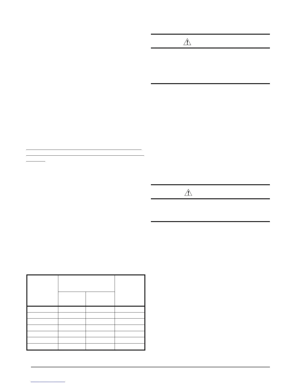
Table 3.
13 SEER Split System Heat Pump Orifi ce
Model
Number
JT5BD-
Restrictor Bore Size
(inches)
System
Charge
R2 (oz.)
Indoor Outdoor
018K 0.053 0.041 93
024KA 0.061 0.047 96
030KA 0.069 0.049 144
036K 0.078 0.057 155
042K 0.083 0.059 248
048K 0.090 0.065 248
060K 0.101 0.071 268
HEAT PUMP MAINTENANCE
WARNING:
To prevent electrical shock, personal injury, or
death, disconnect all electrical power to the unit
before performing any maintenance or service.
The unit may have more than one electrical
supply.
Proper maintenance is important to achieve optimum
performance from the Heat Pump. The ability to properly
perform maintenance on this equipment requires certain
mechanical skills and tools. If you do not possess these
skills, contact your dealer for maintenance. Consult your
local dealer about the availability of maintenance contracts.
Routine maintenance should include the following:
• Inspect and clean or replace air fi lters at the beginning
of each heating and cooling season, or more frequently
if required.
• Inspect the condensate drain and outdoor coil at the
beginning of each cooling season. Remove any debris.
Clean the outdoor coil and louvers as necessary using
a mild detergent and water. Rinse thoroughly with water.
• Inspect the electrical connections for tightness at the
beginning of each heating and cooling season. Service
as necessary.
CAUTION:
The unit should never be operated without a
fi lter in the return air system. Replace disposable
fi lters with the same type and size.
• Do not attempt to add additional oil to motors
unequipped with oil tubes. The compressor is
hermetically sealed at the factory and does not require
lubrication.
REPLACEMENT PARTS
Replacement parts are available through all Nordyne
distributors.
Please have the complete model and serial number of the unit
when ordering replacement parts.
ELECTRICAL:
Capacitors Temperature Limit Switches
Compressors Thermostats
Contactors Time Delay Relays
Pressure Switches Transformers
Relays
MOTORS:
Blower Motor Fan Motor
COMPONENTS:
Blower Assembly Fan Grille
Cabinet Panels Filter/Driers
Expansion Valves
 Loading...