co
ob
NOTES \MG{BLCFoRjWER}
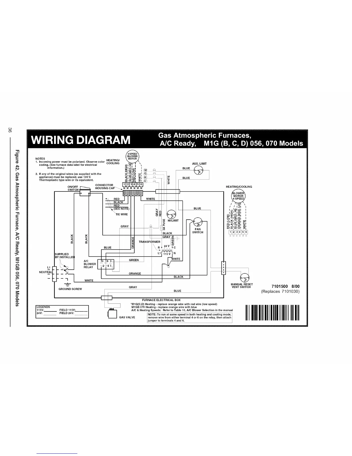
1. Incoming power must be polarized. Observe color HEATING/ _ .._\
coding. (See furnace data label for electrical COOLING _"l_ --\
information.)
2. If any of the original wires (as supplied with the
appliance) must be replaced, use 105°C
Thermoplastic type wire or its equivalent.
L1
NEUT_L
ON/OFF
SWJ.IT._
o o
SUPPLIED
BY INSTALLEI
_1_£1 _J_ _ ............
:_i_j ,,cil = ."J /'-
CONNECTOR Ll121:L41sl6] I/_=
._SIN G CAP""----__
II
II NR,-L,_
BLACK
BLUE I_1 TR/_NSF(:
GREEN J
GROUND SCREW
LEGENDS
115V: FIELD 115V:
24V: FIELD 24V:
AUX. LIMIT
BLUE @_
BLUE
BLOWER
RELAY
WHITE
GRAY z
RMERI/_I''
LI_'_ N
ORANGE
I BLACK
GRAY
BLUE
V
HEATING/COOLING
•1-1"1-1w
I • I I
_=-,_,_, ,
_ _,zl ='
_,,_'=,=_,=,-_'
=t,=!o! _,
MANUAL RESET
VENT SWITCH
__=_G BLUE
FURNACE ELECTRICAL BOX
*M1G(C,D) Heating - replace orange wire with red wire (low speed)
MIGB 070 Heating - replace orange wire with blue
A/C & Heating Speeds: Refer to Table 10, NC Blower Selection in the manual
INOTE: To run at same speed in both heating and cooling mode, I
AS VALVE remove wire from either terminal 4 or 6 on the relay, then attach
jumper to terminals 4 and 6.
7101500 8/00
(Replaces 7101030)
IIIIIIIIIIIIIIIIIIIIIIIIIIII
 Loading...