co
-q
=t3
m,
op
,<_
O'o
of
v i
O
L1
NEUTR-AL'
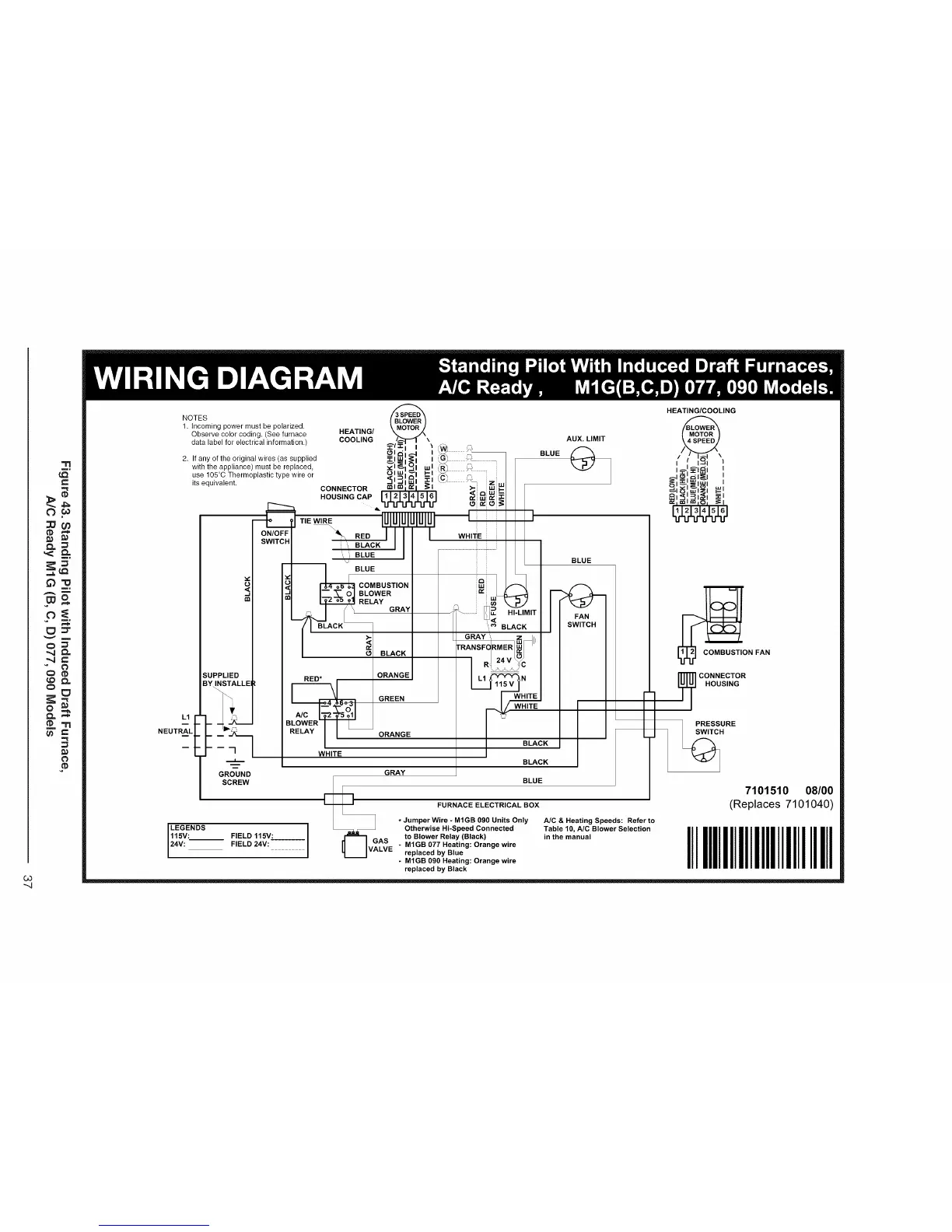
NOTES
1. Incoming power must be polarized.
Observe color coding. (See furnace
data label for electrical information.)
2. If any of the original wires (as supplied
with the appliance) must be replaced,
use 105°C Thermoplastic type wire or
its equivalent.
¢)
SUPPLIED
BY INSTALLEI
GROUND
SCREW
LEGENDS
115V: FIELD 115V:
24V: FIELD 24V:
COMBUSTION
BLOWER
RELAY
GRAY
RED* .
WHITE
BLACK
ORANGE
GREEN
ORANGE
AUX. LIMIT
BLUE
wi "_,
i=i,,,
Mw -LI/liT
L_
_ BLACK
GRAY_ _II
RANSF RMER/ U
I WHITE
I BLACK
BLACK
BLUE
[
GRAY
E_G BLUE
FURNACE ELECTRICAL BOX
* Jumper Wire - MIGB 090 Units Only A/C & Heating Speeds: Refer to
Otherwise Hi-Speed Connected Table 10, A/C Blower Selection
AS to Blower Relay (Black) in the manual
UVALVE " MIGB 077 Heating: Orange wire
replaced by Blue
- MIGB 090 Heating: Orange wire
replaced by Black
HEATING/COOLING
@
_ON FAN
I PRESSURE
,%H
7101510 08/00
(Replaces 7101040)
IIIIIIIIIIIIIIIIIIIIlllIIIll
 Loading...