co
(30
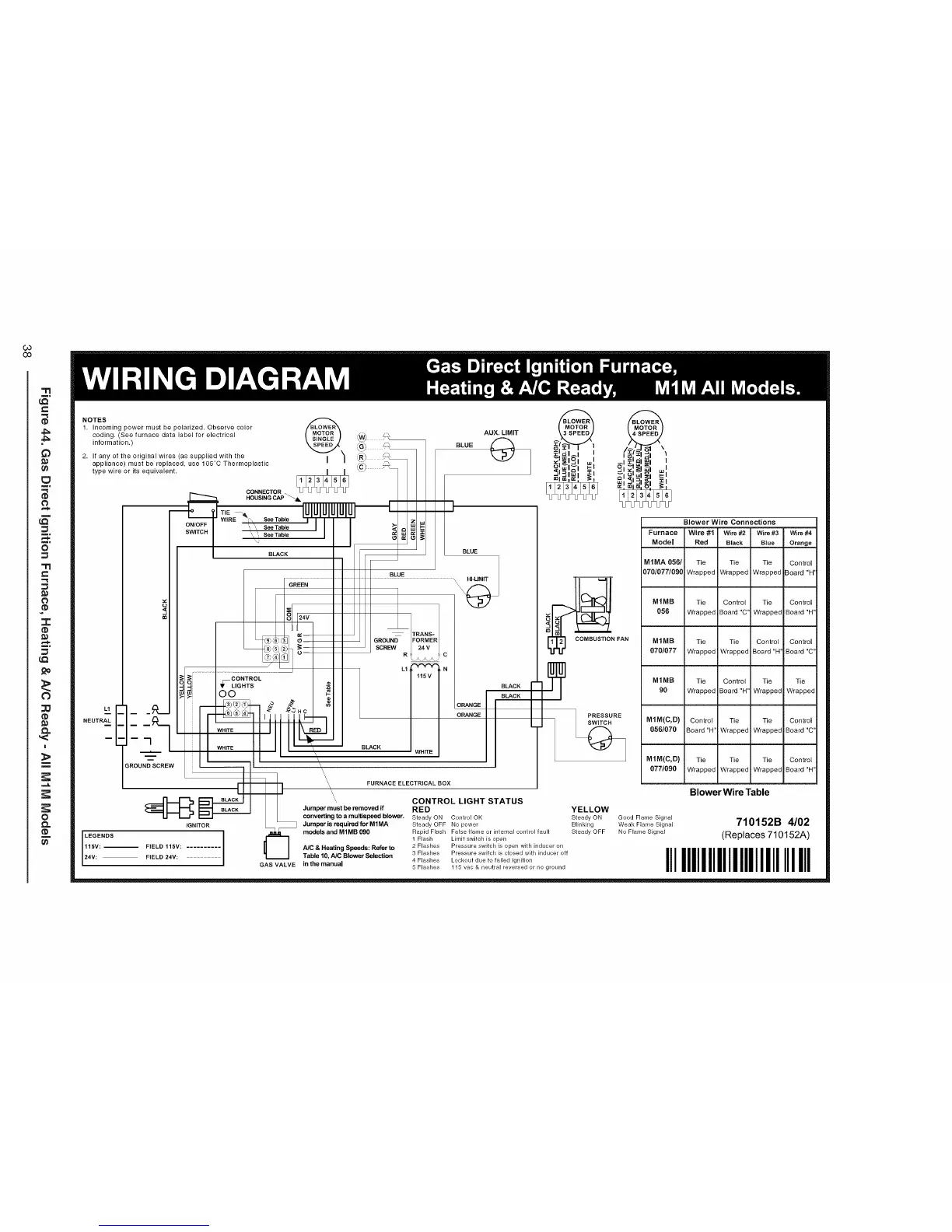
NOTES
1, Incoming power must be polarized, Observe color
coding. (See furnace data label for electrical
information.)
2. If any of the original wires (as supplied with the
appliance) must be replaced, use 105°C Thermoplastic
type wire or its equivalent.
ONIOFF
m
w_
NEUTRAL _--- _ WHITE.....
ROUND SCREW
BLACK
IGNITOR
LEGENDS
115V: -- FIELD 115V:
24V: FIELD 24V:
CONNECTOR
HOUSING CAP
TIE
WIRE Ii\.\ See Table
See Table
BLACK
GREEN
I I
CONTROL
_LIGHTS
DO
_'HC
BLUE
AUX. LIMIT
BLUE
I t BLUE
\
\
\
3
TRANS=
FORMER
24 V
..... 9 c
L1 N
15V
BLACK
H}TB
BLACK I
ORANGE I BLACK
ORANGE
GAS VALVE in the manual
FAN
Blower Wire Connections
Furnace Wire #1 Wire #2 Wire #3 Wire #4
Model Red Black Blue Orange
M1MA 056/ Tie Tie Tie Control
07010771090 Wrapped Wrapped Wrapped Board "H'
MIMB Tie Control Tie Control
056 Wrapped Board "C' Wrappec Board "H"
MIMB Tie Tie Control Control
0701077 Wrapped Wrapped Board"H' Board"C"
MIMB Tie Control Tie Tie
90 Wrapped Board "H' Wrappec Wrapped
MIM(C,D) Control Tie Tie Control
0561070 Board"H" Wrapped Wrappec Board"C"
M1M(C,D) Tie Tie Tie Control
077/090 Wrapped Wrapped Wrappec Board"H"
Blower Wire Table
FURNACE ELECTRICAL BOX
\
\\
CONTROL LIGHT STATUS
Jumper must be removed if RED
convelting to a meltispeed blower. Steady ON Control OK
Jumper is required for M1MA Steady OFF No power
models aod M1MB 090 Rapid Flash False flame or internal control fault
1 Flash Limit switch is open
NO & Heating Speeds: Refer to 2 Flashes Pressure switch is open with inducer on
Table 10, NO Blower Selection 3 Flashes Pressure switch is closed with inducer off
4 Flashes Lockout due to failed ignition
5 Flashes 115 vac & neutral reversed or no ground
YELLOW
Steady ON Good Flame Signal
Blinking Weak Flame Signal
Steady OFF No Flame Signal
710152B 4/02
(Replaces 710152A)
I11IIIIIIIII11111IIIIIIIIII
 Loading...