:ILTER
RETURN AIR
CUT FLOOR
ISTS
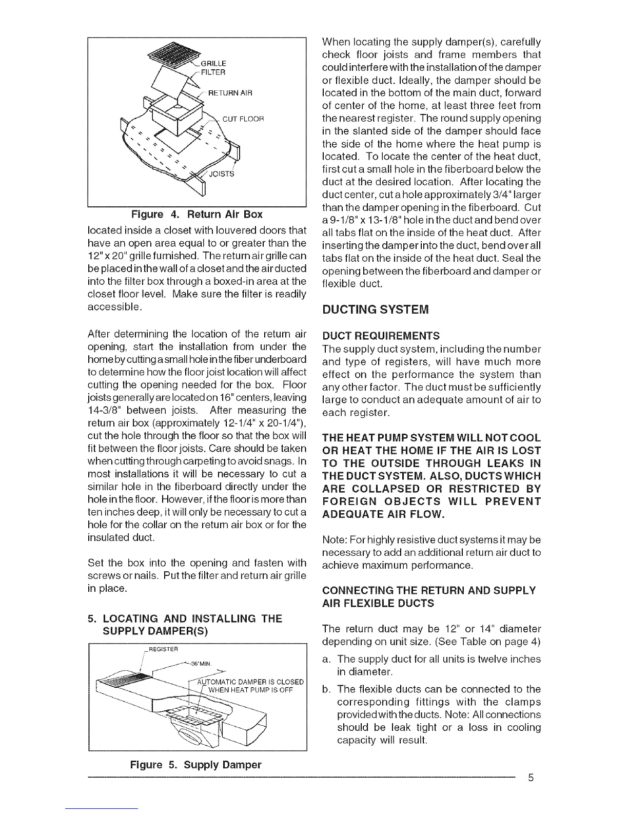
Figure 4. Return Air Box
located inside a closet with Iouvered doors that
have an open area equal to or greater than the
12"x 20" grille furnished. The return air grille can
be placed inthe wall of a closet and the air ducted
into the filter box through a boxed-in area at the
closet floor level. Make sure the filter is readily
accessible.
When locating the supply damper(s), carefully
check floor joists and frame members that
could interfere with the installation of the damper
or flexible duct. Ideally, the damper should be
located in the bottom of the main duct, forward
of center of the home, at least three feet from
the nearest register. The round supply opening
in the slanted side of the damper should face
the side of the home where the heat pump is
located. To locate the center of the heat duct,
first cut a small hole in the fiberboard below the
duct at the desired location. After locating the
duct center, cut a hole approximately 3/4" larger
than the damper opening in the fiberboard. Cut
a 9-1/8" x 13-1/8" hole inthe duct and bend over
all tabs flat on the inside of the heat duct. After
inserting the damper into the duct, bend over all
tabs flat on the inside of the heat duct. Seal the
opening between the fiberboard and damper or
flexible duct.
DUCTING SYSTEM
After determining the location of the return air
opening, start the installation from under the
home bycutting asmall hole inthe fiber underboard
to determine how the floor joist location will affect
cutting the opening needed for the box. Floor
joists gene rally are located on 16" centers, leaving
14-3/8" between joists. After measuring the
return air box (approximately 12-1/4" x 20-1/4"),
cut the hole through the floor so that the box will
fit between the floor joists. Care should be taken
when cutting through carpeting to avoid snags. In
most installations it will be necessary to cut a
similar hole in the fiberboard directly under the
hole in the floor. However, if the floor is more than
ten inches deep, it will only be necessary to cut a
hole for the collar on the return air box or for the
insulated duct.
Set the box into the opening and fasten with
screws or nails. Put the filter and return air grille
in place.
5. LOCATING AND INSTALLING THE
SUPPLY DAMPER(S)
REGISTER
/
/
CLOSED
PUMPISOFF
DUCT REQUIREMENTS
The supply duct system, including the number
and type of registers, will have much more
effect on the performance the system than
any other factor. The duct must be sufficiently
large to conduct an adequate amount of air to
each register.
THE HEAT PUMP SYSTEM WiLL NOT COOL
OR HEAT THE HOME IF THE AiR IS LOST
TO THE OUTSIDE THROUGH LEAKS IN
THE DUCT SYSTEM. ALSO, DUCTS WHICH
ARE COLLAPSED OR RESTRICTED BY
FOREIGN OBJECTS WILL PREVENT
ADEQUATE AIR FLOW.
Note: For highly resistive duct systems it may be
necessary to add an additional return air duct to
achieve maximum performance.
CONNECTING THE RETURN AND SUPPLY
AiR FLEXIBLE DUCTS
The return duct may be 12" or 14" diameter
depending on unit size. (See Table on page 4)
a. The supply duct for all units is twelve inches
in diameter.
b. The flexible ducts can be connected to the
corresponding fittings with the clamps
provided with the ducts. Note: All connections
should be leak tight or a loss in cooling
capadty will result.
Figure 5. Supply Damper
5