3. CONDENSATE DRAIN
Place the desired blower speed lead
on the "NO" terminal of the blower
relay. Use another wire tie (field
supplied) to bundle the remaining motor
lead up and out of the way.
CAUTION'.
To avoid personal injury or property
damage, make certain that the motor
leads cannot come into contact with
any uninsulated metal components of
the unit.
Check all factory wiring per the unit wiring
diagram and inspect the factory wiring connec-
tions to be sure none loosened during shipping
or installation.
Model Wire Color / Motor Air Flow
Q3RD Speed Tap Speed /O.3 In. WC)
Red / T1 Low 750
Orange / T2 Med/Low 1,000
2 Ton T3 Medium 1,140
T4 Med/High 1,300
T5 High 1,350
Red Low 760
2.5 Ton
Black High 1000
T1 Low 750
T2 Med/Low 1,O00
3 Ton Red / T3 Medium 1,140
T4 Med/High 1,300
Orange / T5 High 1,350
Red / T1 Low 1,340
Orange / T2 Med/Low 1,450
3.5 Ton T3 Medium 1,650
T4 Med/High 1,750
T5 High 1,965
T1 Low 1,340
Red / T2 Med/Low 1,450
4 Ton T3 Medium 1,650
Orange / T4 Med/High 1,750
T5 High 1,965
Figure 8. Motor Lead Connection
A 3/4" condensate fitting extends out of the side
of the unit. The drain trap, shipped in the
electrical compartment, must be installed to
prevent water from collecting inside the unit.
Thread the elbow provided with the unit into the
drain connection until hand tight. Install the trap
into the fitting making sure it is level. Route the
condensate from the trap to a suitable drain.
Any tubing or hose connected must have the
outlet below trap level for proper drainage.
WARNING'.
Turn off electrical power before
servicing controls. Severe electrical
shock may result unless power is turned
off. Unit must be installed in compliance
with the National Electrical Code (NEC)
and local codes.
ELECTRICAL CONNECTIONS
1. ELECTRICAL SERVICE
High Voltage
a. Install a branch circuitdisconnectof adequate
size per NEC. Locate the disconnect within
sight of the unit.
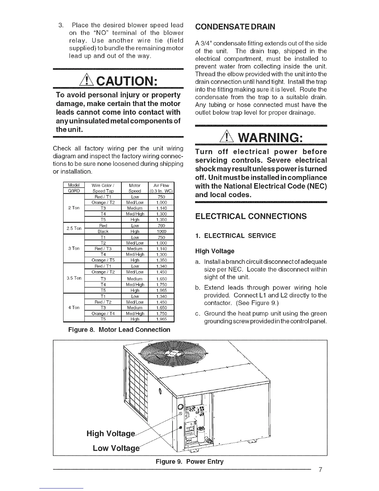
b. Extend leads through power wiring hole
provided. Connect L1 and L2 directly to the
contactor. (See Figure 9.)
c. Ground the heat pump unit using the green
grounding screw provided inthe control panel.
High Voltag
Low Voltag
\
Figure 9. Power Entry
7