40 45
@
0
lo
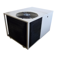
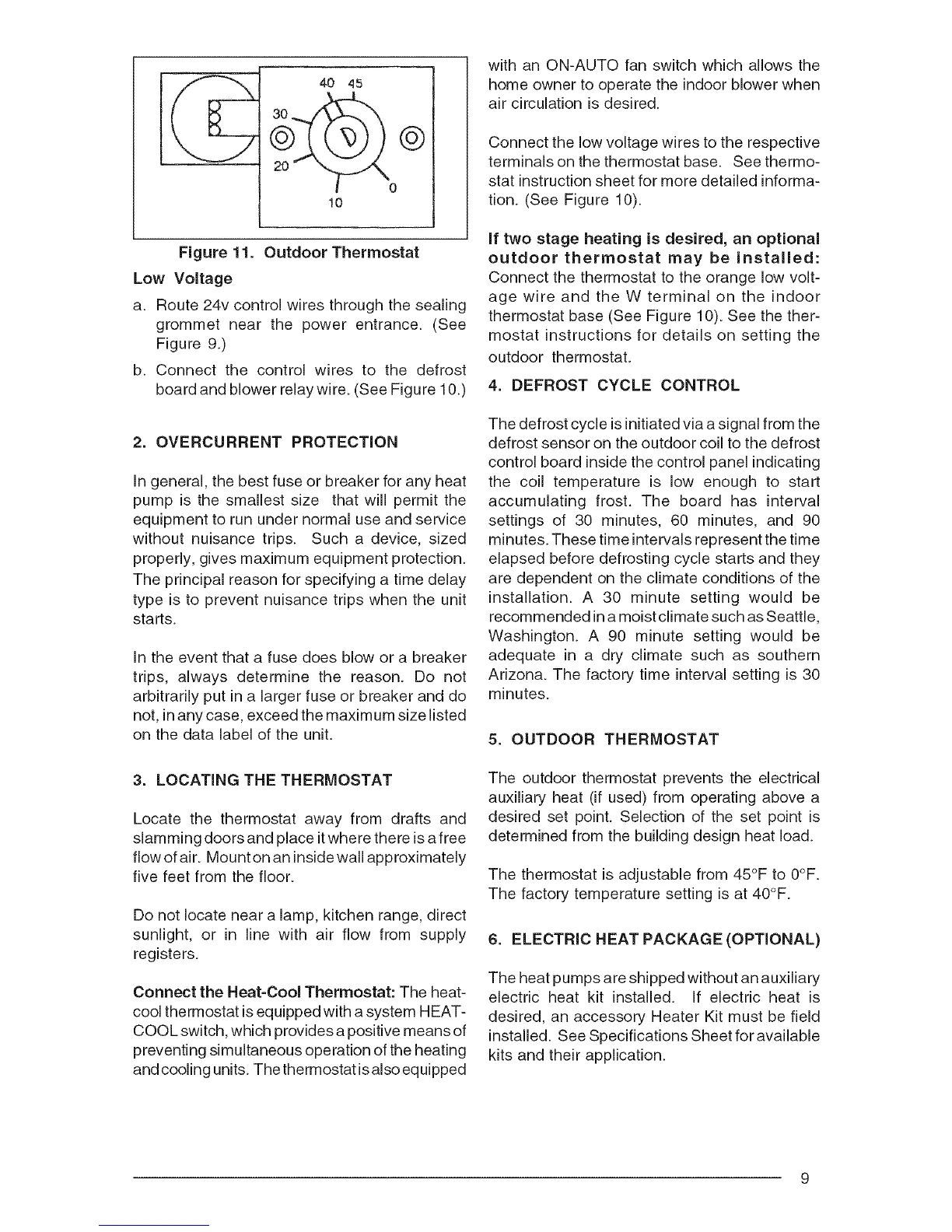
Figure 11. Outdoor Thermostat
Low Voltage
a. Route 24v control wires through the sealing
grommet near the power entrance. (See
Figure 9.)
b. Connect the control wires to the defrost
board and blower relay wire. (See Figure 10.)
2. OVERCURRENT PROTECTION
In general, the best fuse or breaker for any heat
pump is the smallest size that will permit the
equipment to run under normal use and service
without nuisance trips. Such a device, sized
properly, gives maximum equipment protection.
The principal reason for specifying a time delay
type is to prevent nuisance trips when the unit
starts.
In the event that a fuse does blow or a breaker
trips, always determine the reason. Do not
arbitrarily put in a larger fuse or breaker and do
not, in any case, exceed the maximum size listed
on the data label of the unit.
3. LOCATING THE THERMOSTAT
Locate the thermostat away from drafts and
slamming doors and place itwhere there is a free
flow of air. Mount on an inside wall approximately
five feet from the floor.
Do not locate near a lamp, kitchen range, direct
sunlight, or in line with air flow from supply
registers.
Connect the Heat=Cool Thermostat: The heat-
cool thermostat is equipped with a system HEAT-
COOL switch, which provides a positive means of
preventing simultaneous operation of the heating
and cooling units. The thermostat is also eq uipped
with an ON-AUTO fan switch which allows the
home owner to operate the indoor blower when
air circulation is desired.
Connect the low voltage wires to the respective
terminals on the thermostat base. See thermo-
stat instruction sheet for more detailed informa-
tion. (See Figure 10).
if two stage heating is desired, an optional
outdoor thermostat may be installed:
Connect the thermostat to the orange low volt-
age wire and the W terminal on the indoor
thermostat base (See Figure 10). See the ther-
mostat instructions for details on setting the
outdoor thermostat.
4. DEFROST CYCLE CONTROL
The defrost cycle isinitiated via a signal from the
defrost sensor on the outdoor coil to the defrost
control board inside the control panel indicating
the coil temperature is low enough to start
accumulating frost. The board has interval
settings of 30 minutes, 60 minutes, and 90
minutes. These time intervals represent the time
elapsed before defrosting cycle starts and they
are dependent on the climate conditions of the
installation. A 30 minute setting would be
recommended in a moist climate such as Seattle,
Washington. A 90 minute setting would be
adequate in a dry climate such as southern
Arizona. The factory time interval setting is 30
minutes.
5. OUTDOOR THERMOSTAT
The outdoor thermostat prevents the electrical
auxiliary heat (if used) from operating above a
desired set point. Selection of the set point is
determined from the building design heat load.
The thermostat is adjustable from 45°F to 0°F.
The factory temperature setting is at 40°F.
6. ELECTRIC HEAT PACKAGE (OPTIONAL)
The heat pumps are shipped without an auxiliary
electric heat kit installed. If electric heat is
desired, an accessory Heater Kit must be field
installed. See Specifications Sheet for available
kits and their application.