Operator’s manual
Optima 51 / M51 / M56 / M57T / 60T
25
Dynapôle Ludres/Fléville, 166 rue Ampère/BP 60093 - 54714 LUDRES - FRANCE - Tél.+33 (0)3 83 25 69 60 - Fax. +33 (0)3 83 26 12 85
4. Transport position between worksites
When in transport the machine is locked in 4 ways :
-the rst arm is locked by the transport hook (gure 1.25) :
gure 1.25
- lift the rst-arm transport hook all of the way to its stop on the pivot
support with the attached rope.
- raise the rst arm so that the locking pin aligns with the slot in the
transport hook.
- release the hook and ensure that it has fully engaged.
- lower the rst-arm slightly to relieve the load on the hydraulic system.
- move the second-arm in towards the locking buffer.
A captive buffer to lock the second-arm (gure 1.26) :
- the buffer limits movement of the second-arm when
in transport position.
- Do not crush the buffer.
gure 1.26
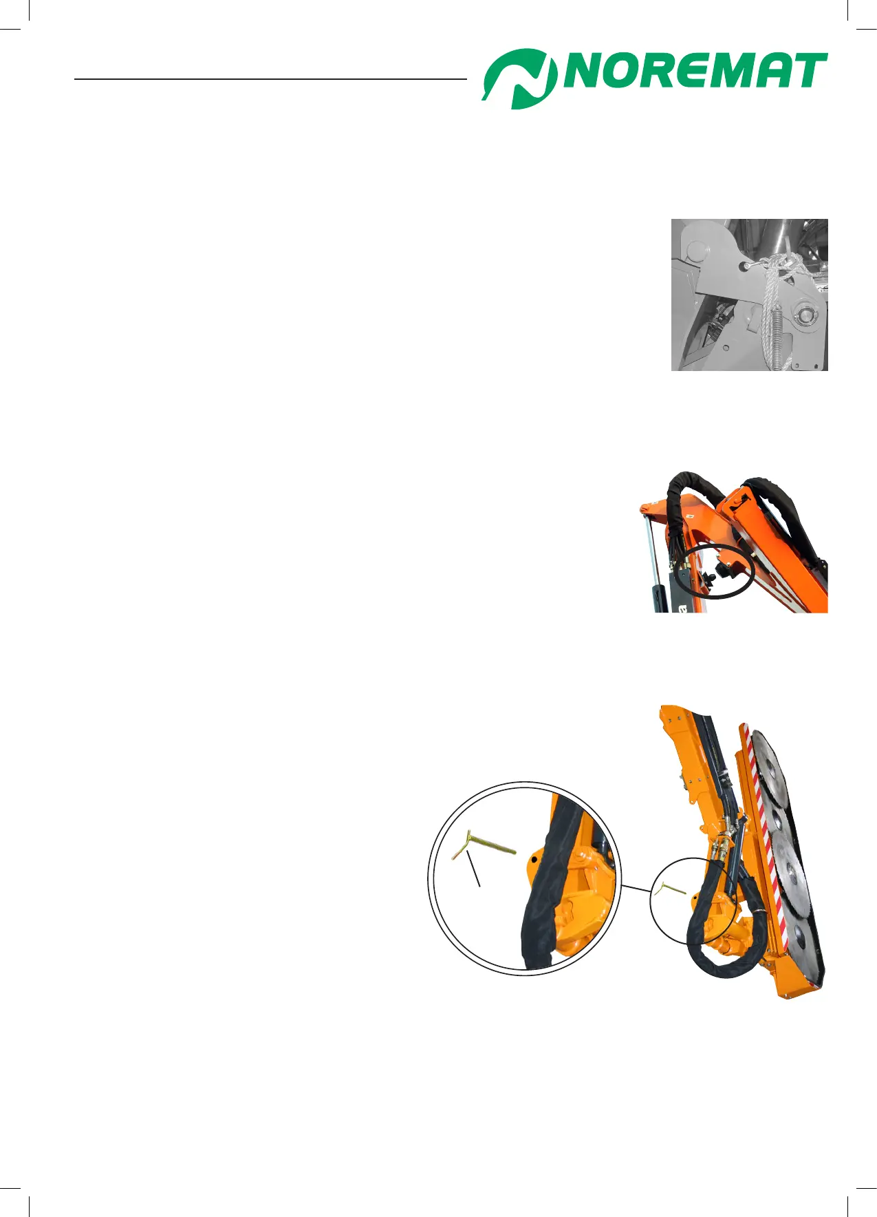
A pin tted to the angle transfer linkage locks the tool: (gure 1.27)
If the machine is tted with a saw-blade unit or reciprocating knife:
-move the tool to the transport position and t the pin through
the transfer plates.
If the machine is tted with a ail cutting tool, place the tool in the horizontal position for transport.
gure 1.27
pin
Technical characteristics