47
YES
Frost sensing switch
32 F or higher
NO
32 F or higher
Heaters turn on
NO
passed
Has 50 min
YES
Heaters turn o
Frost sensing switch
NO
YES
Gas solenoid valve 4
closes
Gas solenoid valve 4
closes
Gas solenoid Valve 3
closes
Main ow control valve closes
Main ow control valve opens
ON
valve 4
Gas solenoid
Over
Warning
indication
Warning indication
19
19
30
30
3
2
triggered (363 F or more)
device (Thermal fuse)
Overheat prevention
3
2
*6
*5
*4
*2
When less than 60 minutes after combustion, it is less than 54 F.
Diers depending on set temperature.
When less than 60 minutes after combustion, it is 50 F or higher.
(as necessary) *2
passed
Has 50 min
Air inlet thermistor
Higher than 30 F
NO
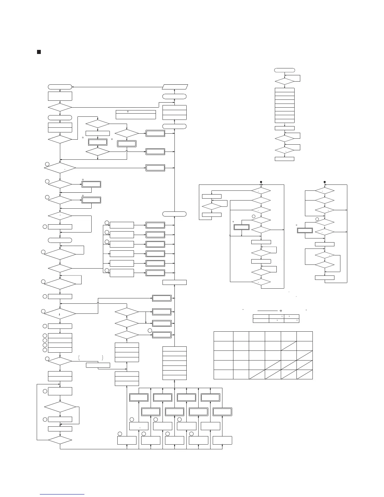
Fan Motor Operation Flow (NR111-SV/N-0931M Only)
*6
NO
normal
NO
Heat
normal
NO
YES
exchanger thermistor
Heat exchanger thermistor
YES
YES
Air inlet thermistor
Air inlet thermistor
34 F or higher
YES
Less than 45 F
NO
NO
Fan motor on
YES
Fan motor stop
YES
YES
Anti-Frost Heater Operation Flow
YES
NO
Air inlet thermistor
41 F or higher
min passed
Has 15 (or 5)
NO
YES
*5
Heaters turn o
min passed
*5
NO
Has 20 (or 50)
YES
Heat
Bypass ow control
valve closes
< 0.4 GPM
Water ow sensor detects
NO
<104 F
exchanger thermistor
Heat
NO
YES
closed
Has 6min. passed
since hot water xture
Fan motor stops
valve opens fully
Main ow control
Fan motor post purge
NO
YES
Hot Water Demand Ceases
Shutdown Procedure
closes
Gas solenoid valve 1
goes o
Gas solenoid valve 3
Gas solenoid valve 2
Gas proportioning valve
Burner On lamp
closes
closes
closes
valve closes
Primary gas solenoid
Heaters turn on
NO
YES
Less than 37 F
Air inlet thermistor
NO
normal
YES
Air inlet thermistor
NO
41 F or higher
YES
exchanger thermistor
ON ON
ONON
ON ON
ON
ON ON
Freeze Prevention Control
NO
normal
YES
Heat exchanger thermistor
valve 3
Gas solenoid
valve 2
Gas solenoid
valve 1
Gas solenoid
Over
BTU
8,000
Over
BTU
20,000
BTU
40,000
Over
ON
BTU
60,000
Over
*3
abnormality
*3 When the present fan speed is 500rpm more or less than target speed.
thermistor
7
open or shorted
Heat exchanger
33
activates
*4
opens
Gas solenoid valve 3
Gas proportioning valve
closes
closes
Gas solenoid valve 2
13
Gas solenoid valve 1
(8 times or less)
Re-ignition
NO
Extinction
YES
(5 times or less)
70
Circuit board
abnormality
33
7
Heat exchanger thermistor
open or shorted
valve closes
Bypass ow control
NO
YES
Setting 145 F or higher
66
NO
normal
control valve operating
Bypass ow
YES
65
NO
normal
YES
Main ow
control valve operating
(Less than 363 F)
device (Thermal fuse) normal
Overheat prevention
possible
Normal combustion
Self-diagnosis
possible
Normal combustion
Self-diagnosis
possible
90
YES
NO
90
Maximum output limited
NO
5 years or more
YES
of use
YES
NO
Current leakage safety
device normal
move to initial position setting
and main ow control valve
Bypass ow control valve
NO (3rd)
YES
is normal
High limit switch
18
120,000
BTU
valve drive circuit
Abnormal gas solenoid
Outlet water temp.
is too high
Flame rod does
not detect a ame
(0.5
μ
A or less)
closes
Gas solenoid valve 1
valve closes
Primary gas solenoid
closes
Gas solenoid valve 2
closes
goes o
Burner On lamp
closes
Gas proportioning valve
closes
Gas solenoid valve 1
valve closes
Primary gas solenoid
opens or closes
Gas solenoid valve
lights
Burner on lamp
Fan motor ON
opens
Gas proportioning valve
valve opens
Primary gas solenoid
opens
Gas solenoid valve 2
Gas solenoid Valve 4
closes
goes o
At max BTU, is
Ignitor stops sparking
temperature check
8
6
5
10
106
5
6
1
8
17
16
15
14
12
11
9
5
4
1
(Fan abnormality)
the code blinking.
The unit will continue to operature with
*1
will be normal (YES).
about K are true , the inlet temprature
or if the following statements
YES
NO
NO
NO
NO
NO
NO
NO
YES
YES
YES
YES
YES
Main ow control valve
Using terms is equivalent
to more than 10 years
99
20
(High-limit switch)
Normal combustion
Self-diagnosis
99
10
YES
NO
Normal
14
NO
YES
90
127 F or more
Less than 127 F
Set temp +9 F136 F
Error code stops ashing
Outlet thermistor
Burner On Lamp
open or shorted
(After 60 sec)
(target 200 rpm)
Water ow sensor detects
If the inlet temp is less than 122 F
K
Set temperature
water inlet temperature ( F)
Approx. 18
Total water ow (GPM)
K >
Disconnect power
Priority lamp turns OFF
Turn power O
Stop hot water demand
72
61
12
11
(Ignition failure)
(Flame rod)
Fan motor stops
Fix problem
71
32
31
open or shorted
Inlet thermistor
31
open or shorted
3216
14
61
Fan speed
Abnormal combustion
*1
Inlet water high
On/O button turn ON
Connect power
Priority lamp (yellow) lights
Ignitor sparks
Flame rod
detects > 1 μA
1st, 4th, 7th:after 5 sec.
others:after 2 sec.
Ignitor stops sparking
Hot water demanded
YES
Initial check
normal
NO
YES
> 0.5 GPM
Fan speed
YES
Inlet thermistor
open or shorted
Outlet thermistor
Flame rod circuit
abnormality
(1μA or more)
outlet water temp. less
than setting
Flow is adjusted
Safety device triggered
NO
Water heating
Warning indication
Warning indication
Warning indication
Warning indication
Warning
indication
NR111 (-SV,-OD,-DV) / NC250 (-SV,-DV)-ASME / N-0931M (-OD,-DV)


 To Next Page