4. OPERATION AND USE
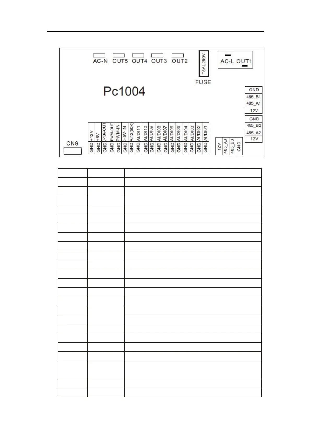
(2) Controller interface diagram and definition
Main board of the input and output interface instructions below
Compressor (output 220-230VAC)
Water pump (output 220-230VAC)
4-way valve (output 220-230VAC)
High speed of fan (output 220-230VAC)
Low speed of fan (output 220-230VAC)
Live wire (input 220-230VAC)
Neutral wire (input 220-230VAC)
System low pressure input
System high pressure input
System suction temperature input
Water input temperature input
Water output temperature (input)
System fan coil temperatureinput
Ambient temperature input
Master-slave machine switch / Antifreeze temperature input
System Exhaust temperature input
Compressor current detection/Pressure sensor (input)
Master-slave machine switch / Feedback signal of EC
fan (input)