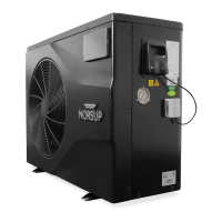
4. OPERATION AND USE
The equipment load is too large
The PFC circuit protection
Check the PFC switch tube short
circuit or not
The IPM module is overheat
Check and adjust the current
measurement
Compressor magnetic force is
not enough
The input voltage lost phase
Check and measure the voltage
adjustment
IPM sampling electricity is fault
Check and adjust the current
measurement
Sensor is short circuit or open
circuit
Inspect and replace the sensor
The transducer is overheat
Check and adjust the current
measurement
Transducer temperature is too
high
Check and adjust the current
measurement
Compressor electricity is large
The compressor over-current
protection
Input current is too large
Check and adjust the current
measurement
Check whether the chip is damaged
Replace the chip
V15V
over/undervoltage
fault
The V15V is overload or
undervoltage
Check the V15V input voltage in
range 13.5v~16.5v or not
(2) Parameter list
Refrigeration target temperature set point
Heating the target temperature set point
Automatic target temperature set point
4.4 Interface draw in
(1) Wire control interface diagram and definition