4. OPERATION AND USE
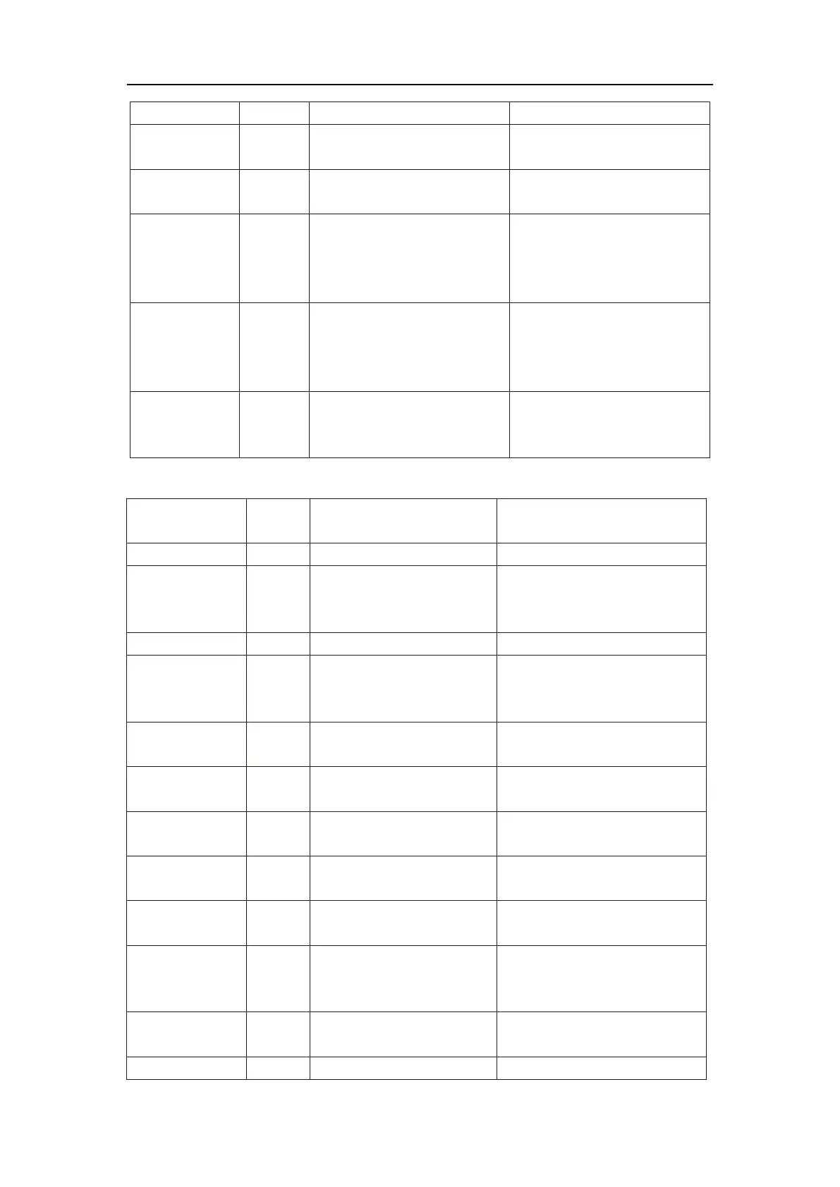
There is something wrong with fan
motor and fan motor stops running
Check whether fan motor is broken
or locked or not
The pressure Sensor is broken
Check or change the pressure
Sensor or pressure
1. Motor is in locked-rotor state
2.The wire connection between
DC-fan motor module and fan
motor is in bad contact
1.Change a new fan motor
2.Check the wire connection and
make sure they are in good contact
1. Motor is in locked-rotor state
2.The wire connection between
DC-fan motor module and fan
motor is in bad contact
1.Change a new fan motor
2.Check the wire connection and
make sure they are in good contact
Communication
Fault (speed
control module)
Speed control module and main
board communication fail
Check the communication
connection
Frequency conversion board fault table:
Frequency conversion board and
main board communication
failure
Check the communication connection
Lack of phase, step or drive
hardware damage
Check the measuring voltage
Check frequency conversion board
hardware
Motor current feedback open
circuit or short circuit
Check whether current return wires
connected motor
IPM Input current is large
Check and adjust the current
measurement
DC bus voltage>Dc bus
over-voltage protection value
Check the input voltage measurement
DC bus voltage<Dc bus
over-voltage protection value
Check the input voltage measurement
The input voltage is low, causing
the input current is high
Check the input voltage measurement
The input voltage is too high,
more than outage protection
current RMS
Check the input voltage measurement
The input voltage sampling fault
Check and adjust the current
measurement
DSP and PFC connect fault
Check the communication connection
 Loading...