4. BETJENING OG BRUG
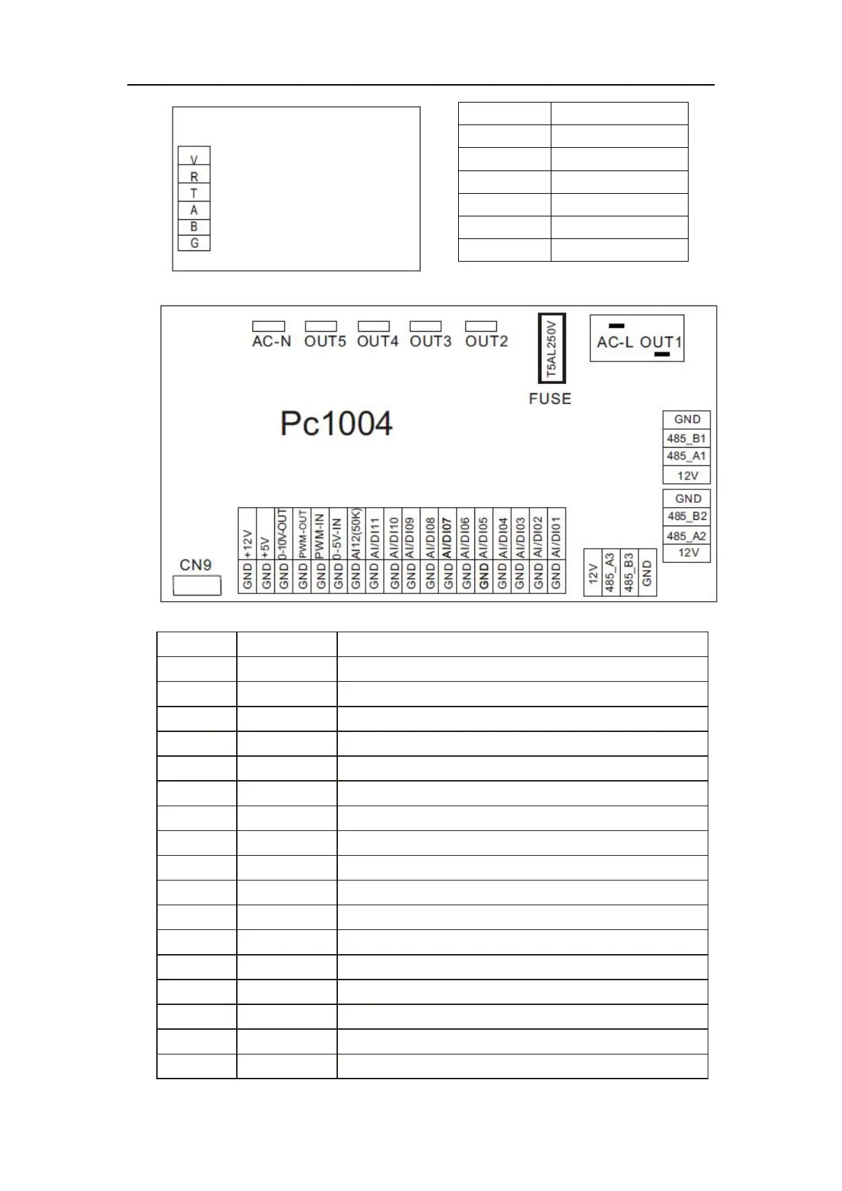
(2) Controllergrænsefladens diagram og definition
Der findes oplysninger om hovedpanelets ind- og udgangsgrænseflader nedenfor
Kompressor (output 220-230 V AC)
Vandpumpe (output 220-230 V AC)
4-vejsventil (output 220-230 V AC)
Høj hastighed for ventilator (output 220-230 V AC)
Lav hastighed for ventilator (output 220-230 V AC)
Strømførende ledning (input 220-230 V AC)
Neutral ledning (input 220-230 V AC)
Kontaktindgang til vandgennemstrømning
Lavtryksindgang for systemet
Højtryksindgang for systemet
Systemudsugningstemperatur indløb
Vandindløbstemperatur indløb
Vandudledningstemperatur (indløb)
Systemventilspoletemperatur indløb
Omgivelsestemperatur indløb