DE
EN
NL
FR
DA
SV
EN
DE
23
Alterations which serve the technological progress as well as errors excepted! ORIGINAL MANUAL NORSUP
WWW.NORSUP.EU Alterations which serve the technological progress as well as errors excepted!
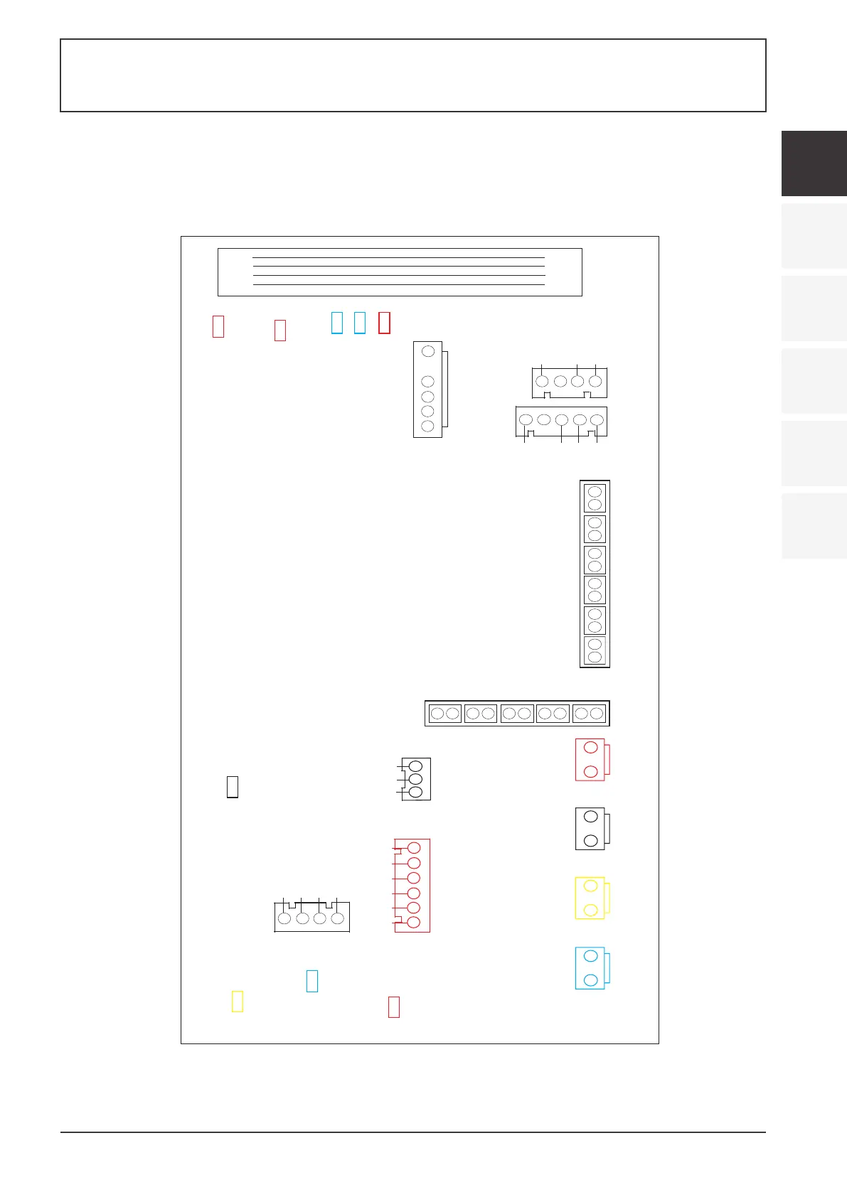
4.4
Interface drawin
(1) Wire control interface diagram and definition
(2) Controller interface diagram and definition
4.10.1 Wire control interface diagram and definition
V
R
T
A
B
G
Sign
Meaning
V
R
T
A
B
G
12V(power+)
No use
No use
485A
485B
GND (power-)
4.10.2 Controller interface diagram and definition
2AC32I27WO1
CN11
CN13
CN18
CN66
CN15(EEV)
CN99(PS)
5V
IN
GND
REMOTE
FS
MODE
LP
HP
CN42
OT
ET
IT
SUT
AT
CT
CN30
1
2 1
111
1
2
2 2
2
2
CN10
RS485-2
A
GND
B
RS485
+12V
A
B
GND
CN97
P10-1(U)
P10-2(V)
P10-3(W)
P14(L)
P13(L)
P1(ACL)
P2(ACN)
P00
LED
12V
A
B
C
D
1
2
3
4
5
6
1
2
3
GND
RESET
5V
TOOLO
2
1
4
3
5
4
3
2
1
3
4
1
2
(2) Parameter list
Meaning
27℃
27℃
27℃
Remarks
Adjustable
Adjustable
Adjustable
Default
Refrigeration
target
temperature set point
Heating the target temperature set point
Automatic target temperature set point
SWIMMING POOL HEAT PUMP TYPE SP
SWIMMING POOL HEAT PUMP TYPE SP