DE
ENNL
FR
DA
SV
EN
DE
25
Alterations which serve the technological progress as well as errors excepted! ORIGINAL MANUAL NORSUP
WWW.NORSUP.EU Alterations which serve the technological progress as well as errors excepted!
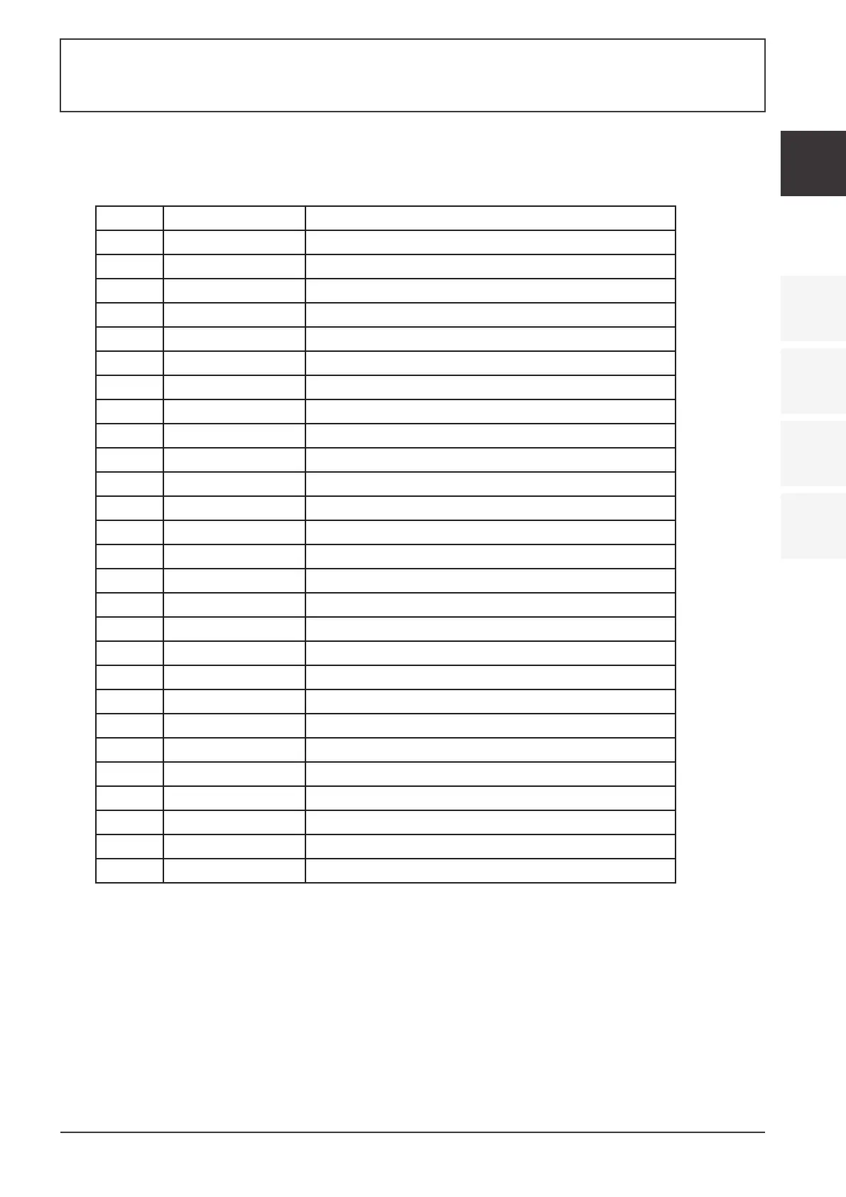
Controller interface diagram and definition
Main board of the input and output interface instructions below
1OW62I23CA2
CN66
CN13
CN18
CN11
CN15(EEV)
CN99(PS)
5V
IN
GND
REMOTE
FS
MODE
LP
HP
CN42
OT
ET
IT
SUT
AT
CT
CN30
1
2 1
111
1
2
2 2
2
2
CN10
RS485-2
A
GND
B
RS485
+12V
A
B
GND
CN97
P10-1(U)
P10-2(V)
P10-3(W)
P14(L)
P13(L)
P1(ACL)
P2(ACN)
P00
LED
12V
A
B
C
D
1
2
3
4
5
6
1
2
3
GND
RESET
5V
TOOLO
2
1
4
3
5
4
3
2
1
3
4
1
2
P10-1/2/3(U/V/W)
Sign
Meaning
Compressor
CN66
CN97
CN11
CN18
CN13
P1
CN10
RS485
Compressor signal
Color line controller communication
DC motor
4-way value
Water pump
Reserved
Live wire
Program download interface
CN15
P13(L)
P14(L)
HP
LP
FS
MODE
REMOTE
IT
Electronic expansion valve
Resistance
System low pressure
Water flow switch
Mode switch
Emergency switch
Water input temperature
System high pressure
SUT
CT
OT
System suction temperature
System fan coil temperature
Water output temperature
ET
AT
CN99
System exhaust temperature
Ambient temperature
Low pressure sensor
RS485-2 The port for centralized control
Resistance
Number
01
02
03
04
05
06
07
08
09
11
12
13
14
15
16
17
18
19
20
21
22
23
10
P2
Neutral wire
P00
Grounding
24
25
26
27
SWIMMING POOL HEAT PUMP TYPE SP
SWIMMING POOL HEAT PUMP TYPE SP