11
5. Insert supply service wire(s) through cable connector(s)
and connect wires to circuit breakers (Figure 14 &
Figure 15). NOTE: To install single-circuit kit, perform
step 5. If single-circuit kit installation is not needed, go
to step 6. A spacer has been provided that must be
installed as a reinforcement where the whip/conduit
enters the unit. Break this spacer in half and use the
appropriate size.
6. To install optional single-circuit kit:
a. Loosen lugs at supply side of circuit breakers.
b. Remove cover from single-circuit kit (if supplied).
c. Insert metal buss bars of kit into lugs of circuit
breaker.
d. Tighten lugs securely (31 in.-lbs. (35 N-m)
recommended).
7. Connect service ground wire(s) to grounding lug(s)
provided. See Figure 16 (page 12). One ground is
required for each supply circuit used.
Grounding
WARNING:
To minimize personal injury, the Appliance
cabinet must have an uninterrupted or unbroken
electrical ground. The controls used in this
Appliance require an earth ground to operate
properly. Acceptable methods include electrical
wire or conduit approved for ground service. Do
not use gas piping as an electrical ground!
Thermostat / Low Voltage Connections
• The Appliance is designed to be controlled by a 24
VAC thermostat. The thermostat’s wiring must comply
with the current provisions of the NEC (ANSI/NFPA
70) and with applicable local codes having jurisdiction.
• The thermostat should be mounted about 5 feet (1.5 m)
above the floor on an inside wall. DO NOT install the
thermostat on an outside wall or any other location
where its operation may be adversely affected by
radiant heat from fireplaces, sunlight, or lighting
fixtures, and convective heat from warm air registers
or electrical appliances. Refer to the thermostat
manufacturer’s instruction sheet for detailed mounting
information. See Figure 20 (page 14) for typical
thermostat connections.
Humidifier
The unit has an output to power a humidifier when the
blower is running during a call for heat. This output is
rated to 1.0 amp at 208V.
Dehumidification Options
The motor control board has a DHUM or D connection
(violet wire) that allows the system to increase the amount
of humidity that is removed from the circulating air. See
Figure 22 (page 18) This is accomplished by reducing the
CFM and allowing the cooling coil to become colder. This
will only occur when there is a call for cooling. There are
many ways that this can be electrically wired.
1. If the room thermostat incorporates a humidity sensor
and DHUM output, connect the DHUM on the thermostat
to the D terminal on the motor control board. See
Figure 22.
2. If using a separate humidistat, connect the DHUM & R
terminals on the humidistat to the D & R terminals on
the motor control board of the air handler. In this option,
the DHUM output of the humidistat must be set so it is
only closed when there is a call for dehumidification.
3. If a humidistat is not available, it is an acceptable option
to connect the R & D terminals on the motor control
board together with a field supplied wire. This option
causes the blower to run at a reduced CFM for 10
minutes after a call for cooling. NOTE: If outdoor unit is
a heat pump, connect the O terminal to the D terminal.
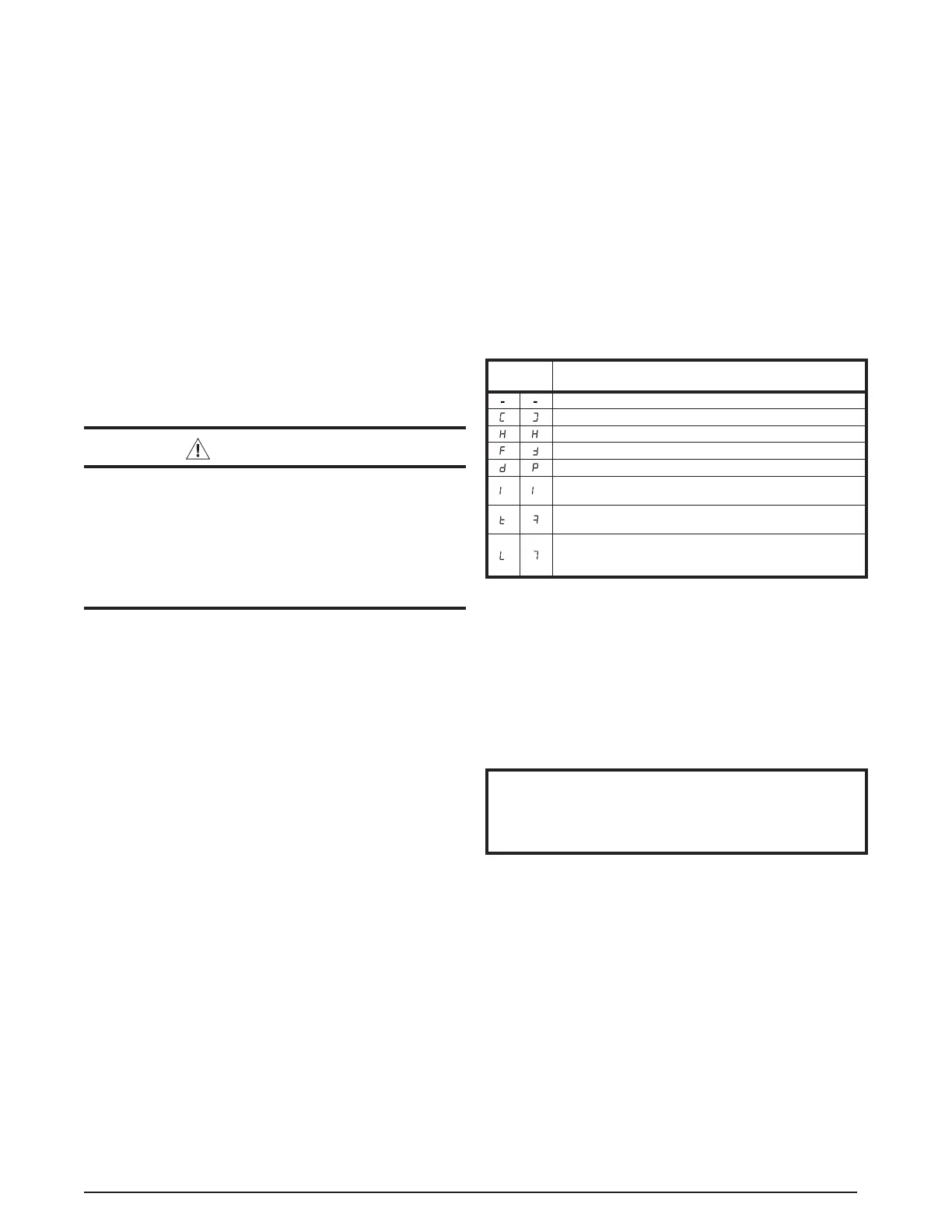
Table 3. FSHE Motor Control Board Display Codes
DISPLAY
CODE
CURRENT MODE
Standby is a Rotating Segment
Cooling Mode (Y input active)
Heating Mode (W input active)
Circulate Fan Mode (G input active)
Dehum Cooling Mode (DEHUM input active along with Y)
(one) A Motor Fault has Occurred (BMF active for more
than 30 seconds)
(lower case t) Over Temperatures (The value of the TS
input has exceeded 80C all outputs are stopped.)
Lockout (Ten (10) or more Motor Faults or Over
Temperature events have occurred. All outputs are set to off
for one hour.
NOTE: Display code may be inverted depending on final installation
orientation.
Electronic Air Cleaner (EAC)
The unit has an output to power an electronic air cleaner
when the blower is running. This output is rated to 1.0
amp at 208V. See Figure 21 (page 17).
Changing Blower Speed
NOTE TO INSTALLER
When the unit is installed, the heating and cooling
speeds must be set for that particular installation.
The installer is responsible for setting these speeds.
Blower speed is determined by the DIP switch settings
located on the unit control board. Pins 1-4 set the speed
for heating. Pins 5-8 set the speed for cooling/heat pump.
Refer to Table 6 (page 17) for allowable heating speeds.
See Table 4 (page 15) and Table 5 (page 16) for blower
performance data.
Installing Control Circuit Wiring
NOTE: Installation of at least a four-wire thermostat
circuit is required. However best practice is to use five-
wire for future addition of a heat/cool thermostat. Any
unused thermostat leads must be properly capped. See
Figure 20 (page 14) for various thermostat connections.
1. Install the 24V control-circuit cable through plastic
bushing at either side of Appliance.
2. Route control circuit wiring to wall thermostat and outdoor
section, if installed.