6
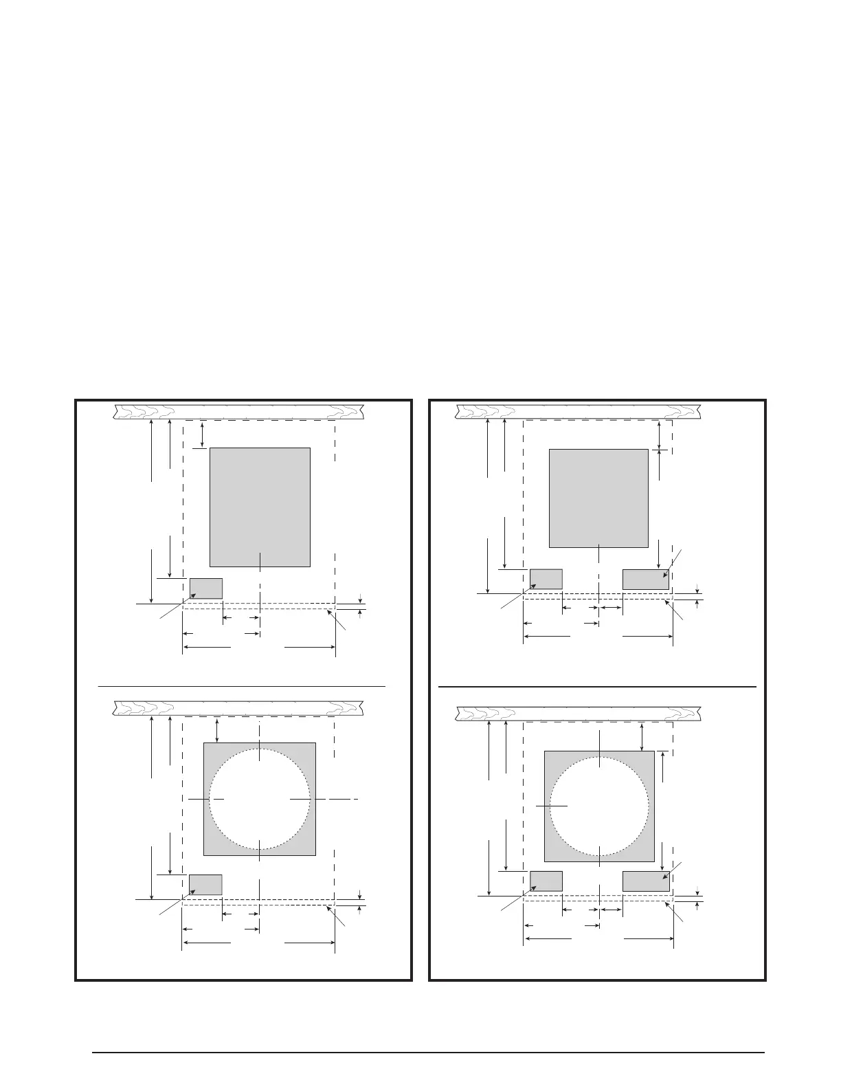
Figure 2. Cut-Out Dimensions for Upflow
Appliances
FLOOR CUT-OUT
17 1/2” (44.4 cm) X
14” (35.5 cm)
FOR UPFLOW
FURNACES WITH
STD. DUCT
CONNECTORS
23 3/4" (60.3 cm)
OPTIONAL
E
3 1/8”
(7.9 cm) X
5 3/4” (14.6 cm)
REAR WALL OF CLOSET OR ALCOVE
FURNACE OUTLINE
FURNACE
DOOR
3”
(7.6 cm)
C
L
20" (50.8 cm)
10" (25.4 cm)
18 5/8" (47.3 cm)
1 3/4" (4.4 cm) MIN.
REAR WALL OF CLOSET OR ALCOVE
FURNACE OUTLINE
FURNACE
DOOR
1 3/4"
(4.4 cm)
MIN.
FLOOR CUT-OUT
14 1/4” (36.8 cm)
DIAMETER FOR
UPFLOW FURNACES
WITH ROUND DUCT
CONNECTORS
C
L
STANDARD DUCT CONNECTOR
ROUND DUCT CONNECTOR
3/4"
(1.9 cm)
3”
(7.6 cm)
20" (50.8 cm)
10" (25.4 cm)
23 3/4" (60.3 cm)
18 5/8" (47.3 cm)
OPTIONAL
E
3 1/8”
(7.9 cm) X
5 3/4” (14.6 cm)
2. Using the centerline as a starting point, draw the rest
of the duct cut-out to the dimensions shown in Figure
2 or Figure 3.
NOTE: Additional provisions may be necessary for
optional air conditioning or heat pump if refrigerant
lines are installed elsewhere than at the front of the
Appliance. The refrigerant and entrance supply opening
dimensions may be adjusted ± 1/2” (13 mm).
3. Cut out the floor opening 1/16” (1.6 mm) larger than
the actual cutout drawn. This will allow some clearance
when installing the duct connector.
4. Measure from the top of the floor down to the top of the
supply air duct to obtain the depth of the floor cavity.
NOTE: The depth of the floor cavity (shown as “X”) in
Figure 4 (page 7) will determine the correct duct
connector.
5. Determine which duct connector to use from Table 2
(page 7).
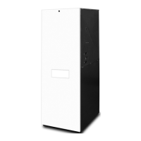
Figure 3. Cut-Out Dimensions for Downflow
Appliances
FLOOR CUT-OUT
14 1/2” (36.8 cm) X
14 1/2” (36.8 cm)
FOR DOWNFLOW
FURNACES WITH
STD. DUCT
CONNECTORS
23 3/4" (6.0 cm)
17" (6.0 cm)
2 3/8" (6.0 cm) MIN.
OPTIONAL
E
4 1/4” (10.8 cm) X
3 3/4” (9.5 cm)
REAR WALL OF CLOSET OR ALCOVE
FURNACE OUTLINE
FURNACE
DOOR
5”
(1.3 cm)
C
L
OPTIONAL SUPPLY
WIRE ENTRANCE
3” (6.0 cm) X
6 1/4” (6.0 cm)
20" (50.8 cm)
3 3/8”
(8.6 cm)
16 5/8" (6.0 cm)
10" (25.4 cm)
REAR WALL OF CLOSET OR ALCOVE
FURNACE OUTLINE
FURNACE
DOOR
FLOOR CUT-OUT
14 1/4” (36.8 cm)
DIAMETER FOR
DOWNFLOW FURNACES
WITH ROUND DUCT
CONNECTORS
C
L
STANDARD DUCT CONNECTOR
ROUND DUCT CONNECTOR
3/4"
(1.9 cm)
3/4" (1.9 cm)
23 3/4" (6.0 cm)
17" (6.0 cm)
2 3/8"
(6.0 cm)
MIN.
OPTIONAL
REFRIGERANT LINE
4 1/4” (10.8 cm) X
3 3/4” (9.5 cm)
5”
(1.3 cm)
OPTIONAL SUPPL
WIRE ENTRANCE
3” (6.0 cm) X
6 1/4” (6.0 cm)
3 3/8”
(8.6 cm)
16 5/8" (6.0 cm)
20" (50.8 cm)
10" (25.4 cm)
Standard Duct Connector Installation
The standard duct connector is designed for use on ducts
12” (305 mm) in width. NOTE: Ducts narrower than 12”
(305 mm) may not allow sufficient clearances for this
type of installation. See Narrow Duct Connector section.
1. Center the duct connector in the floor opening with
bottom tabs resting on top of the supply air duct.
2. Mark the cut-out area on the supply air duct by tracing
around the connector tabs of the duct connector. See
Figure 5 (page 7).
3. Remove the duct connector and cut out the marked
area of the supply air duct 1/4” (6 mm) larger than the
actual cutout drawn.
4. Install the duct connector back in the floor opening with
the bottom tabs extending into the supply air duct.
5. Install the optional mounting plate (Figure 5) under the
back side of the duct connector. Align the screw holes
in both components.