10
ELECTRICAL WIRING
WARNING:
ELECTRICAL SHOCK, FIRE OR
EXPLOSION HAZARD
Failure to follow safety warnings exactly could
result in serious injury, death or property
damage.
Improper servicing could result in dangerous
operation, serious injury, death or property
damage.
• Before servicing, disconnect all electrical
power to Appliance both poles.
• When servicing controls, label all wires prior
to disconnecting. Reconnect wires correctly.
• Verify proper operation after servicing.
CAUTION:
In order to avoid a hazard due to inadvertent
resetting of the THERMAL CUT-OUT, this
appliance must not be supplied through an
external switching device, such as a timer, or
connected to a circuit that is regularly switched
on and off by the utility.
• Electrical connections must be in compliance with all
applicable local codes and the current revision of the
National Electric Code (ANSI/NFPA 70).
• For Canadian installations the electrical connections
and grounding shall comply with the current Canadian
Electrical Code (CSA C22.1 and/or local codes).
Line Voltage Wiring
IMPORTANT NOTES
• Proper line voltage polarity must be maintained for
the control system to operate correctly.
• Circuit breakers installed in this unit provide short-
circuit protection of the internal wiring and serve as
a disconnect. The circuit breakers DO NOT provide
over-current protection of the supply wiring and may
be sized larger than the branch circuit protection.
Overcurrent protection of the supply wiring is
provided by the breaker in the distribution panel
and must be sized as shown in Table 7 (page 18).
It is recommended that the line voltage (230 VAC) to the
Appliance be supplied from a dedicated branch circuit
containing the correct fuse or circuit breaker for the
Appliance. For minimum circuit ampacity and maximum
over-current protection, see Table 7. See unit wiring
diagrams (Figure 23 (page 19), Figure 24 (page 20),
Figure 25 (page 21), Figure 26 (page 22) &
Figure 27 (page 23)) for wiring details. Electrical
components are shown in Figure 16 (page 12).
Supply circuit requirements are listed below:
• -010 model is factory-wired for single-branch supply
circuit only.
• -012 models are factory-wired for single-branch supply
circuit (single-circuit kit factory installed). Dual-branch
circuit can be used by removing factory-installed
single-circuit kit. See Figure 14 (page 10).
• -015, -017, -020 and -023 models are factory-wired for
dual-branch supply circuit. Single-branch circuit can
be used by installing optional single-circuit kit.
Connecting Supply Service Wires
Power entrance for all models may be through the right
side or through the bottom of the unit.
1. Remove right-hand control panel (when viewing in
downflow position).
2. Locate power supply knockouts in side of unit and in
bottom of unit. Remove appropriate plug(s) or knockout
opening applicable to selected wire size(s).
3. For Supply Service Wire installations through the top or
bottom of the appliance. Add bracket for metal thickness
increase for supply wire connections. See Figure 19.
WARNING:
To avoid personal injury or property damage,
make certain that the motor leads cannot
come into contact with non-insulated metal
components of the unit.
4. Install listed cable connector(s) in opening(s). If metal-
sheathed conduit is used for incoming power line(s),
provide an approved metal clamp on conduit and secure
it in entrance knockout.
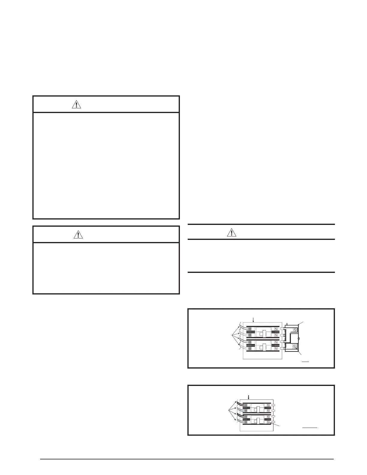
OPTIONAL
SINGLE CIRCUIT
ADAPTOR KIT
CIRCUIT BREAKER
BRACKET
60A
60A
ONON
OFF
OFF
CIRCUIT BREAKER
WIRE ASSEMBLIES
(FACTORY INSTALLED)
SUPPLY SERVICE WIRE
CONNECTION WITH SINGLE
CIRCUIT ADAPTOR KIT
Figure 14. Optional Single Circuit Adaptor Kit
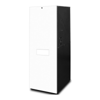
Figure 15. Installation of Supply Service Wires
60A
60A
ON
ON
OFF
OFF
CIRCUIT BREAKER
WIRE ASSEMBLIES
(FACTORY INSTALLED)
CIRCUIT BREAKER
BRACKET
SUPPLY SERVICE WIRE
CONNECTION WITHOUT SINGLE
CIRCUIT ADAPTOR KIT
4. Position optional coil cabinet over floor cutout and
secure with three or more fasteners.
5. Position Appliance onto coil cabinet and secure with
two or more fasteners.
6. Use optional upflow duct connector or field supplied
connector to attach Appliance to overhead supply duct.
See Figure 13.