8
Figure 9. Round Duct Connector Installed
SCREWS
MOUNTING
PLATE
ROUND DUCT
CONNECTOR
14” (36 cm) SUPPLY
CONNECTION
4. Secure the duct connector and the mounting plate to
the wood floor with appropriate size screws.
5. Connect the round supply duct to the underside of the
duct connector and secure them with field supplied
sheet metal screws.
6. Seal all connections with industrial grade sealing tape
or liquid sealant.
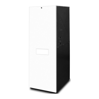
Alcove Installation
1. Cut alcove rough openings to minimum dimensions
shown in Figure 10 (page 8). NOTE: The height may
increase depending on the size of the coil compartment.
2. Attach a return air method to the Appliance. Depending
on the application, this could be a louvered door coil
box, frame and grille assembly, or an upflow stand with
solid door coil box.
Closet Installation
For closet installations, a coil box is recommended to be
installed with the Appliance. In all configurations, return air
must meet requirements found in Minimum Unobstructed
Airflow section. See Figure 11 (page 9).
1. Cut return air opening in desired position in door or
wall. Best practice is above the Appliance. Refer to the
Minimum Unobstructed Airflow section (page 3) for
return air opening requirements.
2. Insert four fasteners, securing grille to door or wall.
Downflow Appliances
For typical unducted return air downflow applications,
an air-conditioner or heat-pump coil can be installed by
mounting the coil directly on top of the Appliance without
adding sheet metal cavities or cutting and trimming wood
panels. Unducted return air systems may be used for
closet or alcove installations.
20"
(508 mm)
24 3/4"
(629 mm)
Coil
Wall
Coil Air
Filters
Return Air Grille
56"
(1423 mm)
29"
( 737 mm)
27"
(686 mm)
Furnace
Front
Wall or Partition
Figure 10. Alcove Installation
The steps below describe installation procedures for
an under-the-floor supply duct system with a ducted
or unducted return air system. Duct connectors are
recommended for this application. See Table 2 (page 7).
NOTE: Remove refrigerant line knockouts in Appliance
only when installing indoor coil of an air conditioner or
heat pump system. Refer to instructions supplied with
accessory equipment.
1. Route supply circuit(s) and 24V wiring to closet
or alcove. See Figure 17 (page 13) or Figure 18
(page 13) for locations. Select appropriate terminal on
unit’s transformer for either 208V or 230V.
2. Remove Appliance front door and slide back until bottom
slots in rear of unit engage with both tabs of optional
rear mounting plate. If mounting plate is not used, an
equivalent method of securing the rear of the unit may
be used as long as it prevents displacement during
transport if used in a manufactured home.
NOTE: The Appliance does not need to be positioned
against the rear mounting plate. The tabs will engage
into the slots and allow approximately 1/2” (13 mm) of
Appliance adjustment front to back and side to side.
3. Secure front of unit with one or more fasteners at
mounting hole(s) provided or at tie-down tab. See
Figure 17 (page 13) or Figure 18 (page 13).
4. See Electrical Wiring section (page 10) to complete
Appliance installation.
Upflow Appliances
The following steps describe installation instructions for
an overhead supply duct system with a return air system
that can be either over the floor (unducted) or through
the floor (ducted).
NOTE: Remove refrigerant line knockouts in Appliance
only when installing indoor coil from an air conditioner or
heat pump system.
Refer to instructions supplied with accessory equipment.
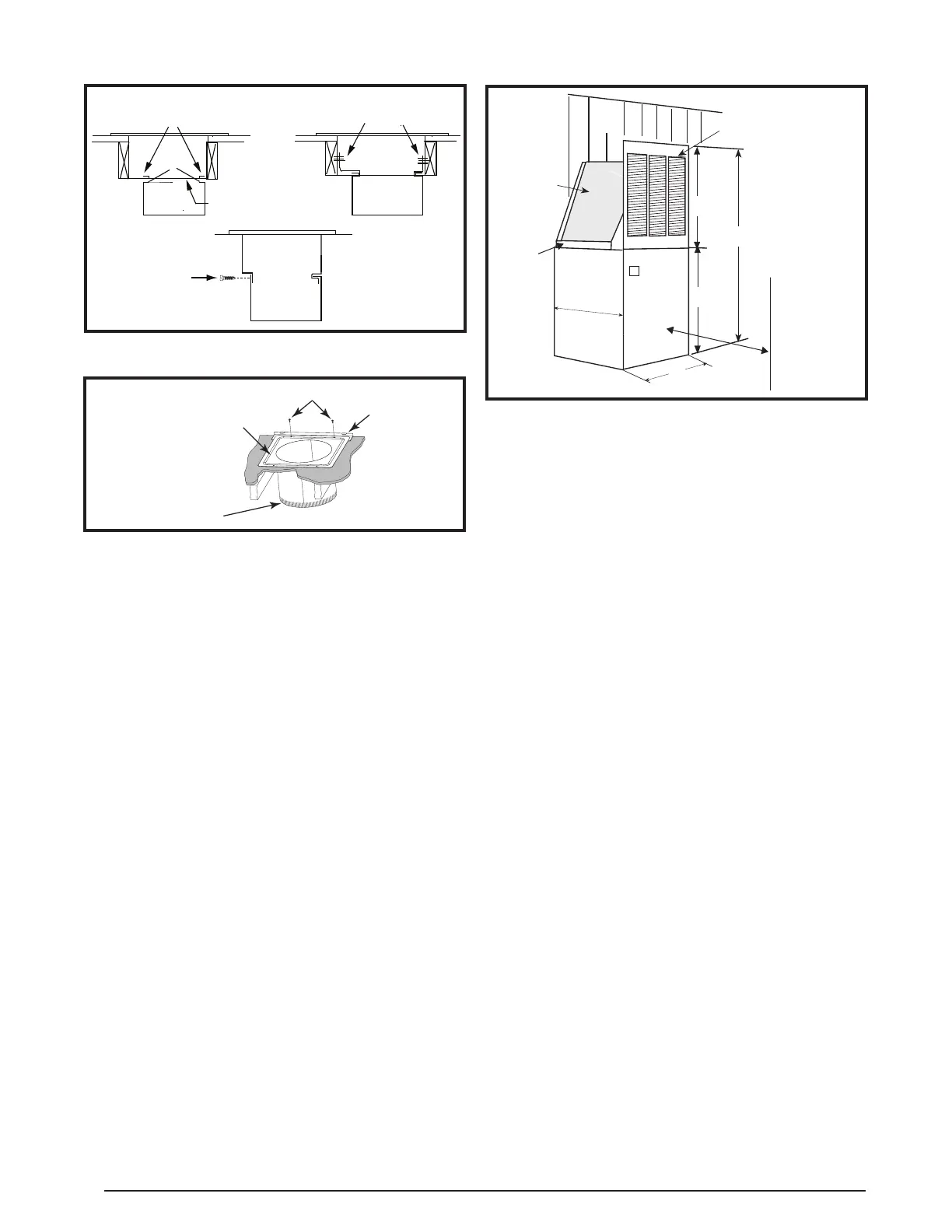
NARROW
DUCT
NARROW
DUCT
DUCT CONNECTOR TABS
STAPLES OR SHEET
METAL SCREWS
DUCT
FLAP
NARROW
DUCT
DUCT
CONNECTOR
SHEET METAL
SCREWS
Figure 8. Narrow Ducts