17
APPLIANCE MODELS E7- 010K 012K 015K 017K 020K 023K
Watts (Total kw, Heating Elements
& Blower)
9.6 11.1 14.2 15.3 18.8 20.2
Supply Voltage 10.4 12.0 15.4 16.6 20.4 22.0
Heating Elements, No. (Total kw) 2 (9.2) 2 (10.7) 3 (13.8) 3 (14.9) 4 (18.4) 4 (19.8)
Motor Speed, H.P. Rating, Amps 2 (10.0) 2 (11.6) 3 (15.0) 3 (16.2) 4 (20.0) 4 (21.6)
Test ESP, in. w.c. Max 0.4
Optional Cooling Available with factory
installed blower
2.0 - 4.0 Ton
Optional Heat Pump Available with factory
installed blower
2.0 - 4.0 Ton
Air Filter (Standard) 18" (45.7 cm) x 20" (50.8 cm) x 1" (2.54 cm) (nominal)
Appliance Dimensions
Multi-Poise
Width-20" (508mm), Height-29" (737mm), Depth-24
1/2" (623mm)
Upflow/
Downflow
Width-20” (508mm), Height-60 5/8” (1546mm),
Depth-24 1/2” (623mm)
NOTE: Heating output rated at listed voltage.
Table 6. Unit Specifications
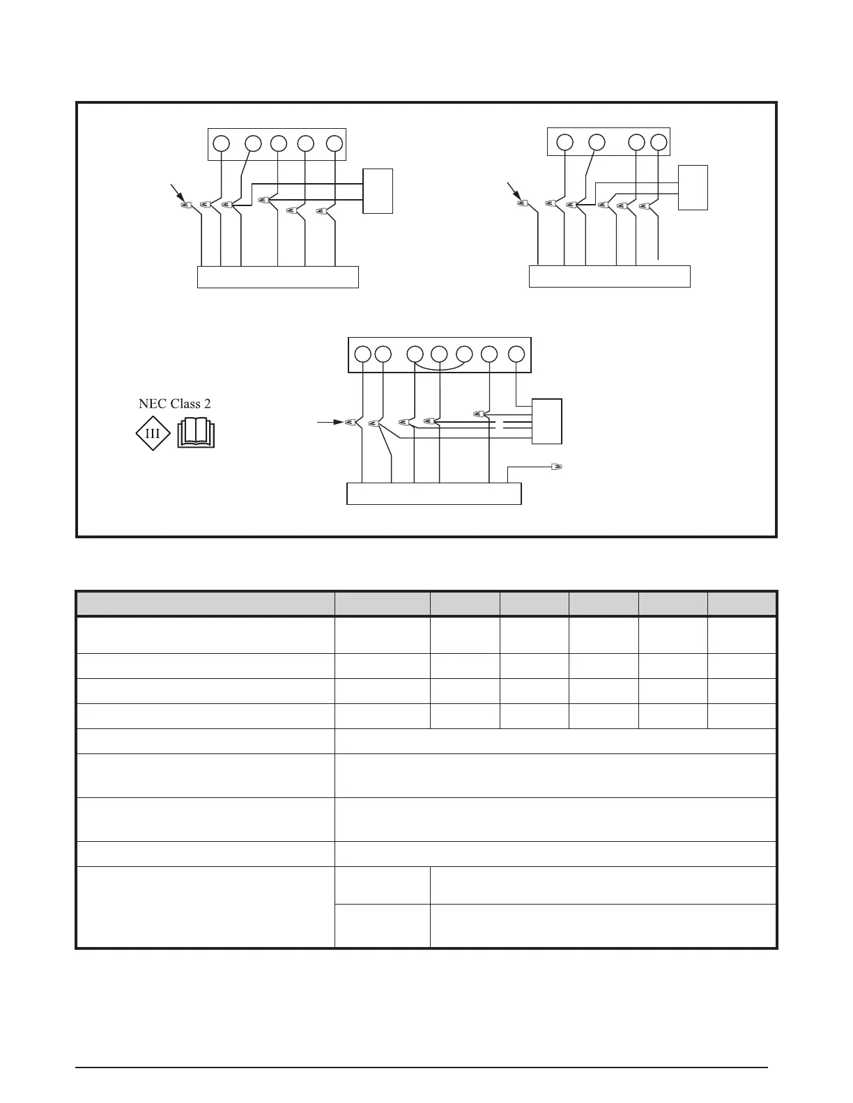
Electrical Data & Diagrams
Figure 21. E7 Thermostat Connection
W
Y
WHITE
GREY
RED
GREEN
4-WIRE THERMOSTAT
WHITE
GREY
RED
GREEN
TO
H/P
HEAT PUMP THERMOSTAT
TO
A/C
G
R
YELLOW
G
R
W2
C
E
Y
O
TO FURNACE CONTROL WIRING
TO FURNACE CONTROL WIRING
WIRE
NUTS
TO FURNACE CONTROL WIRING
YELLOW
W
G
WHITE
GREY
RED
5-WIRE THERMOSTAT
GREEN
Y
R
YELLOW
TO
A/C
WIRE
NUTS
C
VIOLET
WIRE
NUTS
VIOLET
VIOLET
NOTE: For optional dehumidifcation violet wire connection, refer to the Dehumidication Options section.