23
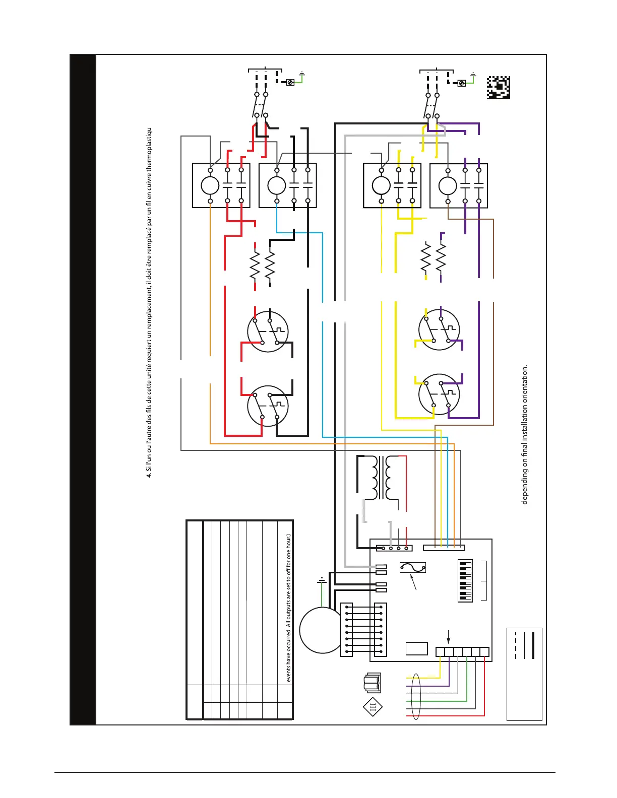
Figure 27. E7EB-020K & E7EB-023K Models
208/230VAC 1Ph/60Hz
10455050
(NEW)
07/23
FIELD WIRING
LEGEND:
LOW VOLTAGE
HIGH VOLTAGE
WIRING DIAGRAM
Model: 20kW and 23kW Electric Furnace with FSHE ECM
NOTES:
1. Supply wire size must be in accordance to the applicable revision of the NEC
and all other applicable codes.
2. To change blower speed refer to installation instructions
3. Refer to appliance installation instructions for thermostat connections.
4. If any wire in this unit is to be replaced it must be replaced with 105° C
thermoplastic copper wire of the same gauge.
5. Not suitable for use on systems exceeding 120V to ground.
6. Refer to installation instructions for complete wiring diagram.
1. La taille du câblage d’alimentation doit être conforme à la révision applicable des codes NEC et des autres codes applicables.
2. Pour changer la vitesse du ventilateur, consultez les instructions d’installation.
3. Consultez les instructions d’installation de l’appareil pour les branchements du thermostat.
e 105 °C du même
gabarit.
5. Ne convient pas à l’utilisation sur les systèmes qui excèdent 120 V à la terre.
6. Consultez les instructions d’installation pour un schéma de câblage complet.
DISPLAY
CODE
CURRENT MODE
-
Standby is a Rotating Segment
C
Cooling Mode (Y input active)
H
Heating Mode (W input active)
f
Circulate Fan Mode (G input active)
d
Dehum Cooling Mode (DEHUM input active along with Y)
I
(one) A Motor Fault has Occurred (BMF active for more than
30 seconds)
t
(lower case t) Over Temperatures (The value of the TS input
has exceeded 80C all outputs are stopped.)
L
Lockout (Ten (10) or more Motor Faults or Over Temperature
-
C
H
f
d
I
t
L
MAIN AIR
LIMIT
BACKUP
LIMIT
L1 L2
R
C
G
W
D
Y
MOTOR
FIELD CONNECTION
TO THERMOSTAT
DC RELAY
DC RELAY
DC RELAY
DC RELAY
R
L1
L2
C
ELEMENT
ELEMENT
ELEMENT
ELEMENT
8
NEC Class 2
STANDARD (ATO)
AUTOMOTIVE
BLADE-TYPE
FUSE, 3 AMP,
32VDC MAX
HEAT
OFF
ON
COOL
1 2 3 4 5 6 7 8
CONTROL BOARD
TRANSFORMER
208V
230V
MAIN AIR
LIMIT
BACKUP
LIMIT
CIRCUIT B
CIRCUIT A
SUPPLY VOLTAGE
L1
L2
SUPPLY VOLTAGE
L1
L2
YELLOW
YELLOW
YELLOW
YELLOW
VIOLET
VIOLET
BROWN
GRAY
GRAY
VIOLET
VIOLET
VIOLET
YELLOW
VIOLET
YELLOW
BLUE
GRAY
ORANGE
RED
RED
RED
RED
BLACK
BLACK
GRAY
BLACK
WHITE
RED
BLACK
NOTE: DISPLAY CODE may be inverted
BLACK
BLACK
RED
GRAY
BLACK
WHITE
OPTIONAL DEHUM
RED
BLACK
YELLOW