Northstar Explorer 657 Installation and Operation Manual76
Black
Yellow
Blue
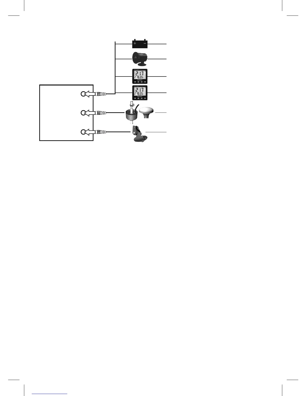
Connections
Power (18-4)
External alarms (18-4)
NavBus instruments (18-9) and VHF
radio (18-8)
NMEA out to instruments (18-10)
GPS antenna (18-5), Petrol/gasoline
sensors (18-7), NMEA in (18-10)
Sonar transducer (18-6)
Display unit
(18-3)
Power/data cable
Pin Wire Function
1 Black Ground: - power in, NMEA ground. (The cable has two black wires which are
connected inside the cable and it does not matter which black wire you use)
2 Brown Not used
3 White NMEA out
4 Blue NavBus-
5 Red Power in, +10.5 V DC to +30.5 V DC
6 Orange NavBus+
7 Yellow Auto power in
8 Green External alarm out, 30 V DC 200 mA maximum.