7
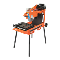
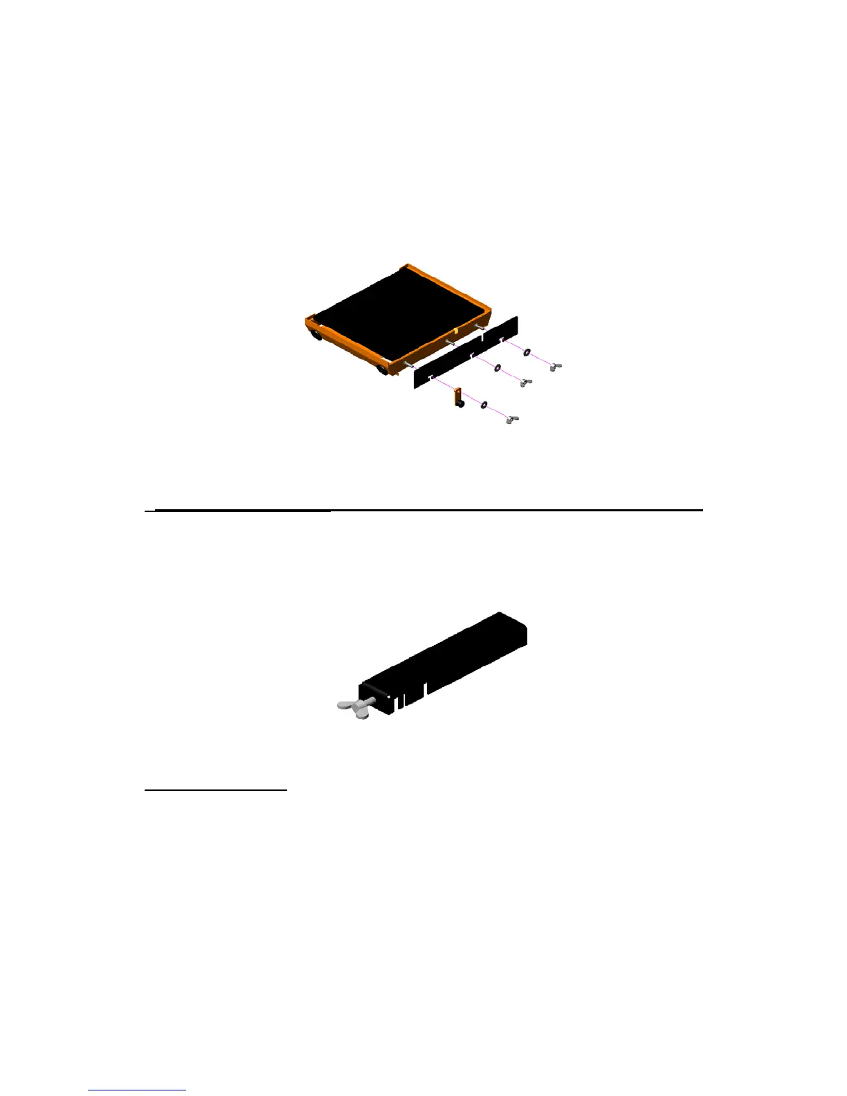
Conveyor Cart Assembly:
Remove the Conveyor Cart and Back Stop from the Saws Water Pan, and the
Wing Nuts, Carriage Bolts, Washers, and Cart Stop from the plastic bag. Slide
one (1) Carriage Bolt thru each of the three (3) Square Holes located on the
front of the Conveyor Cart. Slide the Back Stop Over each of the Carriage
Bolts. Slide the Stop Assembly over the Carriage Bolt Located on the Left front
of the Conveyor Cart NOTE: The Rubber Stop will faces away from the
Conveyor Cart. Attach one (1) Washer and one (1) Wing Nut to each Carriage
Bolt and Tighten. See Figure 1: Back Stop Assembly. Place the Conveyor
Cart on the Machine.
Figure 1: Back Stop Assembly
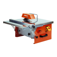
Guide-A-Cut Assembly:
Attach the Guide-A-Cut to the Conveyor Cart by adjusting the Wing Bolt until
the Guide-A-Cut can slide over the Black Stop. The Guide-A-Cut will work as a
Rip Guide that is adjustable for 90 and 45 cuts. See Figure 2: Guide-A-Cut
Assembly.
Figure 2: Guide-A-Cut Assembly
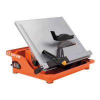
Splash Assembly:
Remove the Splash Guard from the Saw Water Pan. Attach the Splash Guard
Spring Clips to the Pivoting Bar Located Under the Cutting Head. Note that the
rough side of the Splash Guard should face towards the front of the saw. The
Splash Guard material is made is designed for easy to cleaning. To clean,
simply rinse the Splash Guard with water until clean. The Splash Guard should
be used when wet cutting to reduce the amount of debris thrown from the blade
and cutting surface. When dry cutting the Splash Guard can be removed to
allow the dust particles to drift away from the Saw Operator.