Maintenance Instruction
54
4.7 Hydraulic Lifting Mechanism Adjustment
Position the farm implement lifting handle in the neutral position, as shown in the figure, and then adjust the
distance between the block on the push rod and the bumper pin fixed on the lifting shaft. The lifting position of the
farm implement can then be controlled.
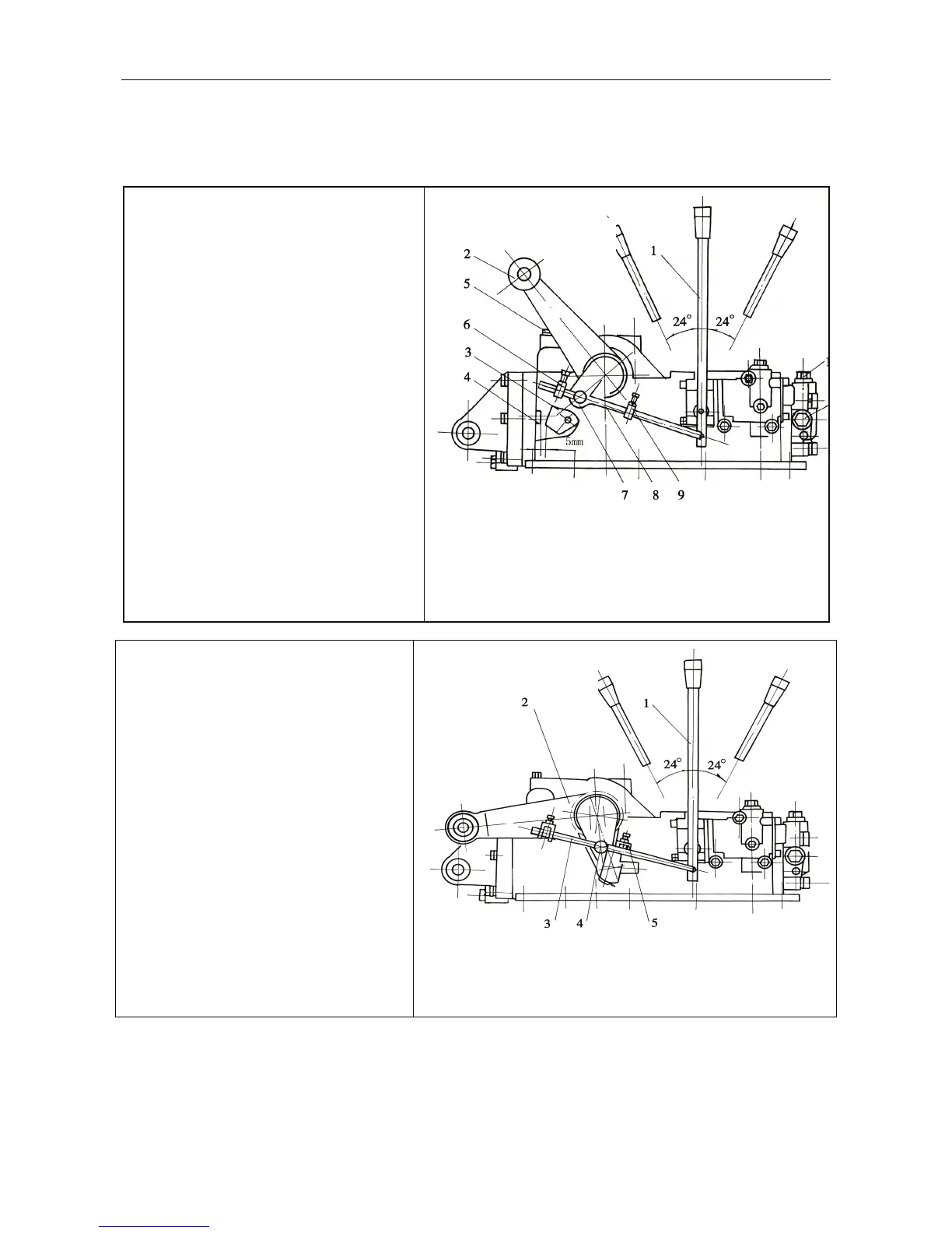
4.7.1 Hi
Position
Adjustment of Farm Implements
During the adjustment, turn the external
lifting arm (2) outwards first to adjust the
distance between the lower end of the internal
lifting arm (3) and the limiting pin (4) of the
cover of back end of the riser to be 5mm
(insert a block of about 5mm thick at the air
plug (5). Adjust the distance between the
lifting bstop (6) and bumper pin (7) to be 9–
10mm, and fix the block (6) on the return rod
(8) with the bolt, and lock the nut with the
bolt.
Figure 4-17 Adjustment of Lifting Position
1. Handle 2. External lifting arm 3. Internal lifting arm
4. Limiting pin 5. Air plug 6. Lifting stop 7. Bumper pin
8. Push rod 9. Lowering stop
10. Hydraulic output plug screw 11. Adjusting valve
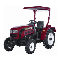
4.7.2 Lowest Position Adjustment
of Farm Implements
During the adjustment, turn the external
lifting arm (2) downwards to the lowest
position (at this time, the piston in the oil
cylinder is pushed nearly to the lowest point).
Adjust the distance between the lowering stop
(5) on the return push rod (3) and bumper pin
(4) to be 9–10mm, and then fix the stop (4) on
the push rod with the bolt and nut.
Figure 4-18 Lowering Position Adjustment
1. Handle 2. External lifting arm 3. Push rod 4.
Bumper pin 5. Lowering stop
lifting
neutral
lowering
lifting
neutral
lowering