- 4 -
2. GENERAL REQUIREMENTS AND SPECIFICATIONS
This unit must be installed in a dry place, in a non-corrosive, well-ventilated environment, without excessive dust. The
ambient temperatue must be over 10°C and under 27°C. If the ambient temperatue is 10°C or less, the plenum must be
insulated on 10 ft linear minimum length.
CAUTION
1. LOCATION - The furnace should be centrally located to the heating area.
2. POSITIONS - It can be installed for vertical, horizontal or downflow operation. When installed horizontally, the furnace should be positioned such as the
door will not end up being on the top. The door should be on the side of the furnace, to ensure that the motor bearings are in their designed position. In
vertical downflow installations, use only “L”- or “T”-shaped plenum with no openings or registers directly below furnace.
3. INSTALLATION CLEARANCES - As shipped from the factory, each unit is approved for “zero inch” clearance. If additional clearance is required, it will be
indicated on the data label attached to the furnace.
4. TEMPERATURE RISE - Furnaces are shipped to operate at 0.20” W.C. (50 Pa) external static pressure. They are certified for operation up to
0.50” W.C. (125 Pa). Check below for temperature rise table on specification chart and, if necessary, adjust the unit to match.
5. SERVICE CLEARANCE - Units are serviced from the FRONT. Leave at least 24” (610 mm) clearance in front of the door.
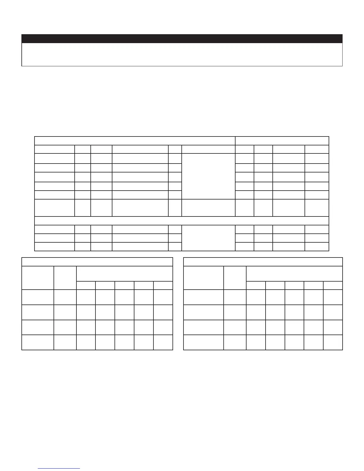
240 VOLTS - SINGLE PHASE TEMPERATURE RISE @ 0.20” W. C.
MODEL NO. KW BTHU AMPS INCL. MOTOR HP BLOWER
°C °F *SPEED RPM
21B10M 10 34152 46 1/3
10” x 8”
(254 mm x 203 mm)
23 41 LOW 663
21B15M 15 51228 67 1/3 24 43 MED-LOW 814
21B18M** 18 61473 77 1/3 27 49 MED-LOW 814
21B20M** 20 68304 86 1/3 33 59 MED-LOW 814
21B25M** 25 85379 107 1/3 37 67 MED-LOW 814
21B27MS***† 27 92210 116 3/4
12” x 8”
(304 mm x 203 mm)
36 65 MED-HIGH 707
208 VOLTS - THREE-PHASE
83B13 13.5 46105 42 1/3
10” x 8”
(254 mm x 203 mm)
21 38 MED 960
83B24 24 81964 70 1/3 35 63 MED 960
83B27 27 92210 78 1/3 39 70 MED 960
10” x 8” (254 mm x 203 mm) BLOWER
SPEED
FLOW
RATE
STATIC PRESSURE
(INCHES OF WATER COLUMN)
0.2 0.3 0.4 0.5 0.6
LOW
CFM
L/s
756
357
749
353
740
349
729
344
713
337
MED-LOW
CFM
L/s
1035
488
1018
480
997
470
971
458
935
441
MED-HIGH
CFM
L/s
1177
556
1157
546
1132
534
110 2
520
1063
502
HIGH
CFM
L/s
1301
614
1276
602
1247
588
1207
569
1145
540
12” x 8” (304 mm x 203 mm) BLOWER
SPEED
FLOW
RATE
STATIC PRESSURE
(INCHES OF WATER COLUMN)
0.2 0.3 0.4 0.5 0.6
LOW****
CFM
L/s
727
343
699
330
667
315
636
300
606
286
MED-LOW****
CFM
L/s
912
431
897
423
878
414
853
402
823
388
MED-HIGH
CFM
L/s
1216
574
1200
566
1181
557
1157
546
1129
533
HIGH
CFM
L/s
1640
774
1601
755
1558
735
1513
714
1466
692
WARNING:
*FACTORY SETTINGS.
** 21B18M, 21B20M and 21B25M must NOT be setup to run continuously at LOW speed as it will cause overheating conditions. These models are
certified to run only at HIGH, MED-HIGH and MED-LOW speeds.
*** 21B27MS must NOT be setup to run continuously at LOW or MED-LOW speeds, as it will cause overheating conditions. This model is certified to run
only at HIGH and MED-HIGH speeds.
****These speeds can only be run with heater off, for cooling/ventilation purposes only.
†21B27MS has built-in additional noise-absorption components to run quietly during continuous or regular cycle modes.
SPECIFICATIONS SUBJECT TO CHANGE WITHOUT NOTICE