- 8 -
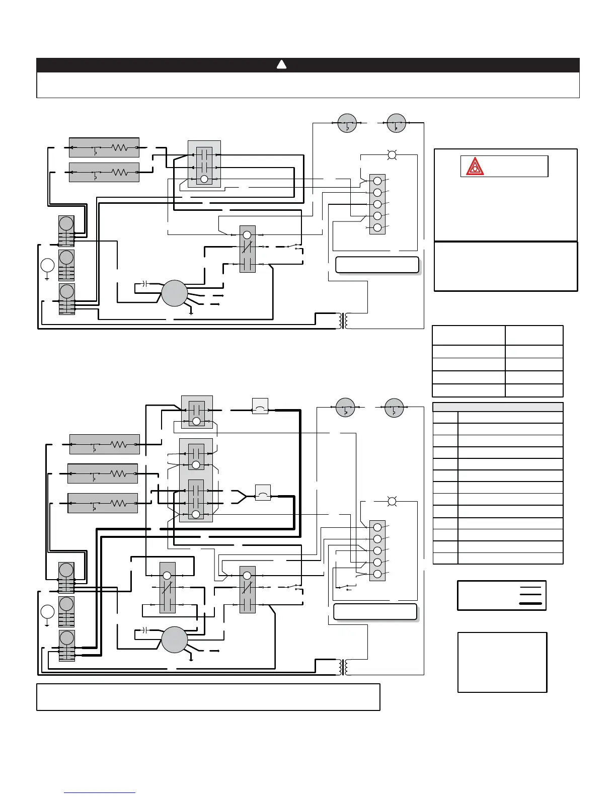
8. WIRING DIAGRAMS
!
WARNING
Risk of electric shock. Disconnect power before installation, servicing, maintenance or field wiring. Replace all panels
before operating. Failure to do so can result in electric shock causing severe injuries or death.
FE0045A
Class 2 Transformer
Pri: 240 V 60 Hz
Sec: 24 V 60 Hz 40 VA
HEAT 2
E
ARTP
R
24 VAC
COMMON OUT
24 VAC
POWER OUT
CALL FOR FAN
CALL FOR
HEAT 1
CALL FOR
HEAT 2
R
ARTP
E
HEAT 1
B
B
R1
M2
M4
M1
M3
24V
DC
B
B
B
BL
BL
W
B
HEAT INDICATOR
W
Open: 93.3°C
MRTP 1 MRTP 2
C
G
R
W1
W2
TB
Y
B
BL
Y
10 KW 240 VAC
Single phase
T
Y
Y
B
R
K1 24V
1
5
2
3
6
4
R
Continuous
Ventilation
B
24V
DC
R
BL
Y
B
C
O
B
M
L1
L2
N
G
R
B
BL
1. If any of the original wire, as supplied, must
be replaced, use the same equivalent wire.
Wiring must comply with applicable codes,
ordinances and regulations.
2. Field wiring must comply with applicable
codes, ordinances and regulations. Use only
Class 1 wiring inside furnace compartments.
Critical characteristic
Line voltage wiring:
UL AWM 1015/1230, 600V, 105°C, VW-1, 12 AWG;
CSA TEW 600V, 105°C, FT1, 12 AWG.
Low voltage wiring:
same ratings as high voltage except 18 AWG.
HI
MED-HIGH
MED-LOW
LOW
FAN MOTOR SPEED
BLACK
BLUE
YELLOW
RED
COLOR
LEGEND
C
E
R
K
MRTP
HEAT
L1, L2
Capacitor
Heating Element
Time Delay Relay
Fan Relay
Auto-Reset Thermal Protector
Manual-Reset Thermal Protector
240 V Line Supply
WIRING COLOR CODE
B BLACK
BL BLUE
O ORANGE
R RED
W WHITE
Y YELLOW
ARTP
M
TB
T
N
Fan Motor
Terminal Block
Transformer Class 2
Heat
Neutral
B Breaker
For the use of a two-stage thermostat or an outdoor thermostat, connect between W1 and W2.
Make sure that the Season Select switch is set to “Mild” position.
Low power
High power
High power 8 AWG
HEAT 2
E
ARTP
R
HEAT 3
E
ARTP
R
HEAT 1
E
ARTP
R
B
B
B
B
R2
M2 M1
24V
DC
BL
R1
M6 M5
24V
DC
BL
M2 M1
M4 M3
24V
DC
BL
BL
R
R
B2
B1
25 A
50 A
R
B
B
B
BL
L1
L2
N
G
R
B
O
C
M
B
K1 24V
1
5
2
3
6
4
24V
DC
K2 240V
1
5
2
3
6
4
240
VAC
NC
B
R
Y
BL
B
BL
R
Continuous
Ventilation
B
B
BL
BL
W
BL
BL
B
24 VAC
COMMON OUT
24 VAC
POWER OUT
CALL FOR FAN
CALL FOR
HEAT 1
CALL FOR
HEAT 2
HEAT INDICATOR
C
G
R
W1
W2
TB
BL
Season Select
B
Y
15 KW 240 VAC
Single phase
Y
Class 2 Transformer
Pri: 240 V 60 Hz
Sec: 24 V 60 Hz 40 VA
T
Y
Y
B
R
W
Open: 93.3°C
MRTP 1 MRTP 2
21B10M Model
21B15M Model