Voice Alarm Multiplex 15889:F2 10/01/01
1111
1111
11
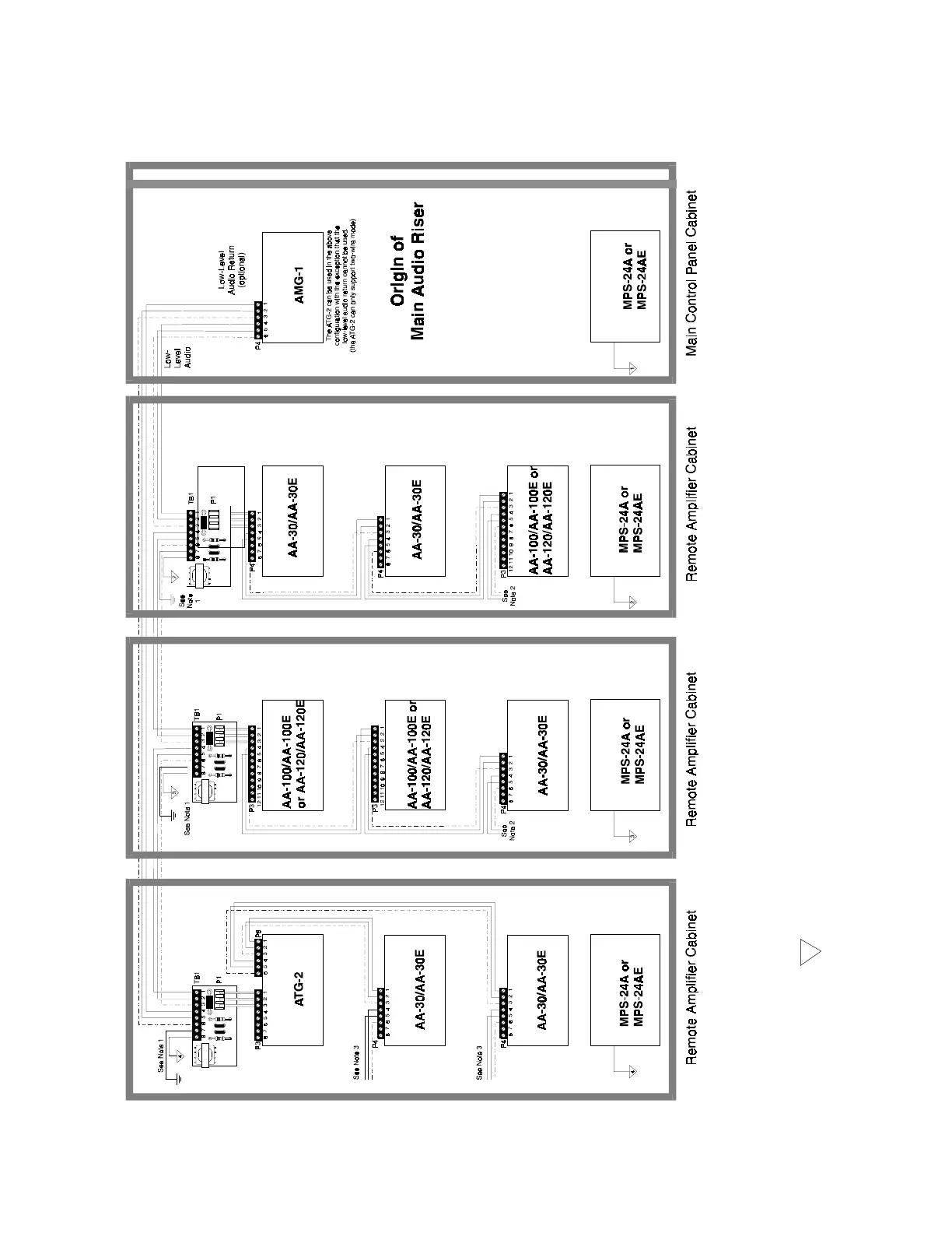
Note 1:
Using the supplied cable, connect the "EARTH" ground terminal of each ACT-1 to terminal P8-10 on the AA-100/AA-100E or AA-
120/AA-120E or to a screw on the upper left corner of the AA-30/AA-30E. The "COM" terminal is intended for optional shielding
of the secondary side of the ACT-1 (the low level audio from the ACT-1 through each of the amplifiers). If this shield is desired,
connect to the common of the local power supply (do not, at any point connect the shield from the primary side of the ACT-1).
Note 2:
The secondary side of the ACT-1 (low-level audio) may be daisy chained to a maximum of eight audio amplifiers.
Note 3:
Additional low-level audio risers, isolated from the main riser, may be drawn from this point.
Note 4:
3 This symbol denotes a local common, in this case for supply number three.
Note 5:
A maximum of seven ACT-1 Audio Coupling Transformers may be connected to the AMG or VTG (primary side). The number of
amplifiers connected to the primary side of the ACT-1 (AMG/VTG output) must be reduced by eight for each ACT-1 connected,
regardless of the number of amplifiers connected to the secondary side of each ACT-1
51
 Loading...


