ML0021 August 15, 2018
107 Copyright 2018 Bitronics, LLC
CB CB CB
9
VA1
10
VB1
11
VC1
12
VN1
6
C
HI
5
B
HI
4
A
HI
1
A
LO
3
C
LO
2
B
LO
13
VA2
14
VB2
15
VC2
16
VN2
26
C
HI
25
B
HI
24
A
HI
21
A
LO
23
C
LO
22
B
LO
VOLTAGE
CURRENT
BUS 1
VOLTAGE
CURRENT
BUS 2
A
B
C
N
ABCN ABCN
LINE 1 LINE 2
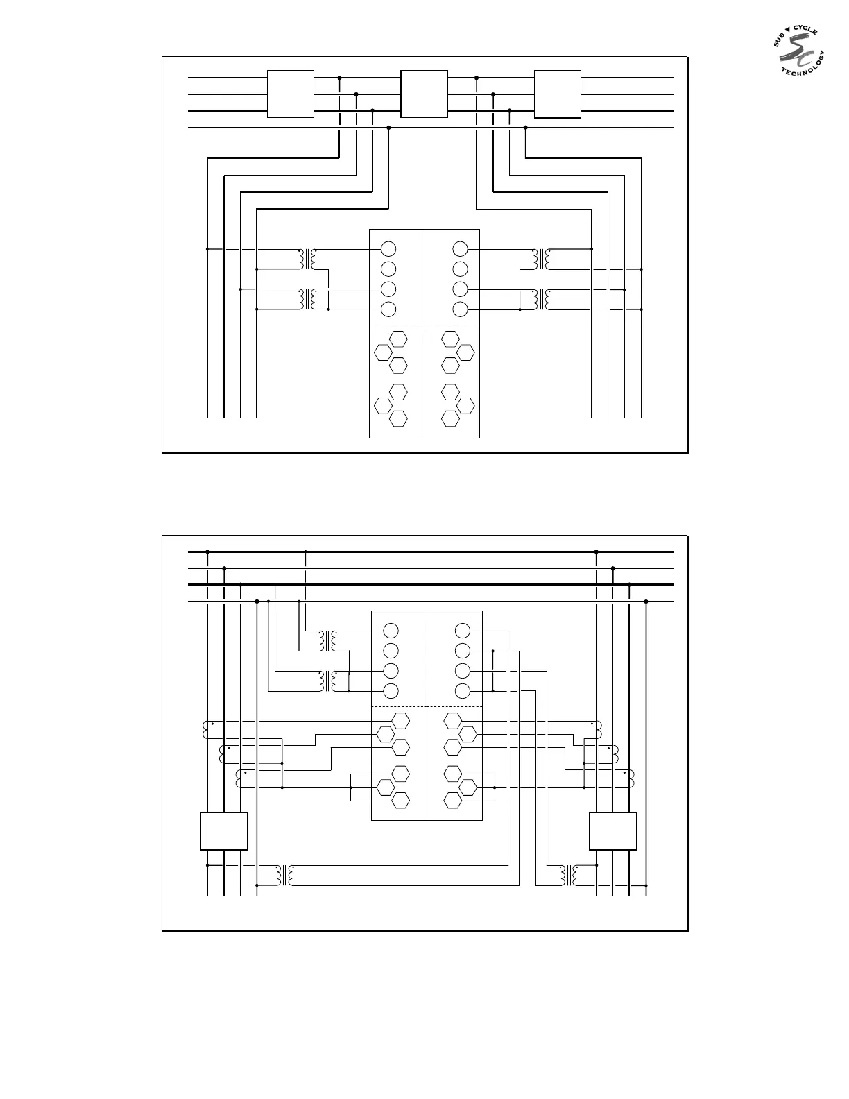
2½ Element (Wye) configured for Breaker-and-a-Half (voltage connections shown, with B-phase missing)
Current connections are the same as for 3-element 4-wire (wye) shown on the preceding page.
When configuring the unit, set the VT ratio for the missing phase equal to 0. This will cause the M872 to calculate the
voltage of the missing phase from the vector sum of the two phases present (assumes balanced voltage).
LOAD
ABCN
9
VA1
10
VB1
11
VC1
12
VN1
6
C
HI
5
B
HI
4
A
HI
1
A
LO
3
C
LO
2
B
LO
13
VR1
14
VRN1
15
VR2
16
VRN2
26
C
HI
25
B
HI
24
A
HI
21
A
LO
23
C
LO
22
B
LO
VOLTAGE
CURRENT
BUS 1
VOLTAGE
CURRENT
BUS 2
CB CB
LOAD
ABCN
A
B
C
N
BUS (POTENTIALS COMMON TO BOTH FEEDERS)
FEEDER 1
FEEDER 2
“Reference” potentials VR1
and VR2 are intended for
synch-check across the
respective feeder-breakers.
2½ Element (Wye) configured for Dual Feeder Common Bus (shown with B-phase missing).
When configuring the unit, set the VT ratio for the missing phase equal to 0. This will cause the M872 to calculate the
voltage of the missing phase from the vector sum of the two phases present (assumes balanced voltage).
Figure 9 - Signal Connections (M872)