ML0021 August 15, 2018
111 Copyright 2018 Bitronics, LLC
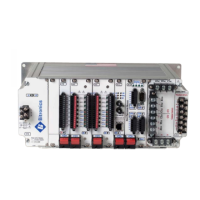
8.8 Cabling
The Ethernet interface uses a RJ-45 connector for copper interfaces and ST connectors
for the optional fiber interfaces. "Straight-through" copper cables rated Category 5 (Cat5)
or above up to 100 meters (328 feet) in length can be used The cable used for the P1x
modules MUST be 100Ω STP (shielded twisted pair) for proper EMI/RFI performance. For
the E1 or E3 options UTP (unshielded twisted pair) cable is satisfactory for the network
connection. If a connection to a non-networked PC is desired, a "cross-over" cable can be
used between the Ethernet card and the PC. Category 3 (Cat3) cable is not
recommended due to the lack of upgradeability to 100 Mb Ethernet. Fiber-optic cable up
to 2000 meters (6500 feet) in length (412 meters or 1350 feet for 100 Mb half-duplex) can
be used. The cable should be multimode glass with a 62.5 mm core and 125 mm cladding
(62/125), ST connectors for the M87x end and proper terminations for the network end
(either ST or SC). The M87x supports only one Ethernet connection.
8.9 Connections
Copper network connections are made by simply plugging in the two cable ends. Ensure
that the network end terminates in a port that is not labeled "uplink". An optical connection
is made by connecting the TX port of the Ethernet interface to the RX port of the network
hub or switch. The RX port then connects to the TX port. Use of external equipment using
SC connectors is possible by using properly terminated cable or adapters. A few seconds
after connection, green LINK indicators at each device should illuminate to indicate a
proper connection has been established.
8.10 Troubleshooting the Connection
If a link is not established, verify that the RX and TX signals are not swapped (either by
misapplying a "cross-over" cable or an "uplink" port or swapping the optical cables). If a
connection is still not made, refer to Section 8.13.2 for suggestions.
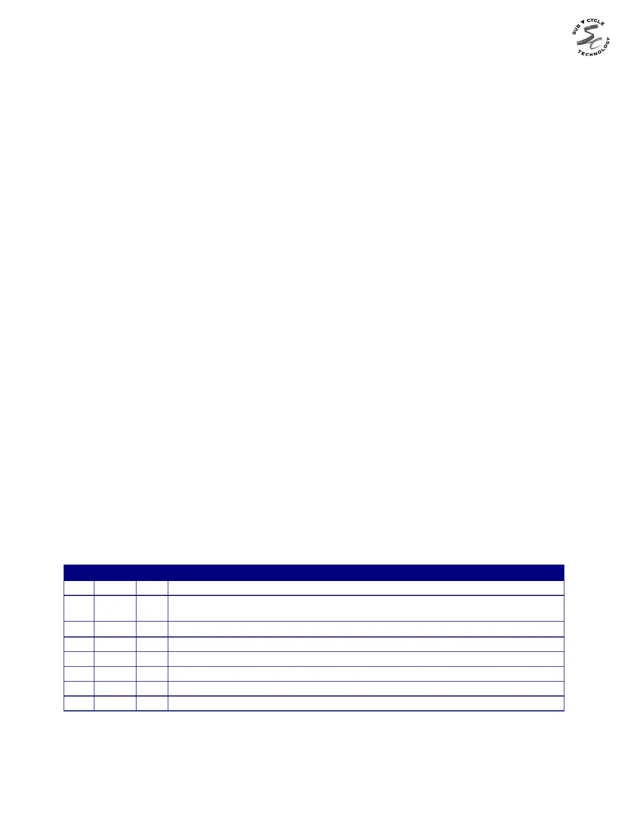
8.11 Indicators
The Ethernet interface has six LEDs for use by users on the P1x modules, but only two
LEDs on the E1 or E3 option.
LED
FUNCTION
P1x E1 E3E3
LK LNK
Indicates a valid Physical connection. Must be on before any communicates takes
place.
100
On when operating at 100 Mb, off for 10 Mb. Valid only when LINK is on.
COL
Flashes when an Ethernet collision occurs. See explanation below.
FULL FULL
On when operating in full-duplex mode, off for half-duplex.
TX
Flashes when packet is being transmitted
RX
Flashes when any packet is being received (even packets not addressed to this
ACT ACT Flashes activity when packets are transmitted and received
The collision LED, in particular, is a good indication of network health. It lights whenever
the M87x and another device attempt to use the link at the same time (by definition, full