ML0021 August 15, 2018
127 Copyright 2018 Bitronics, LLC
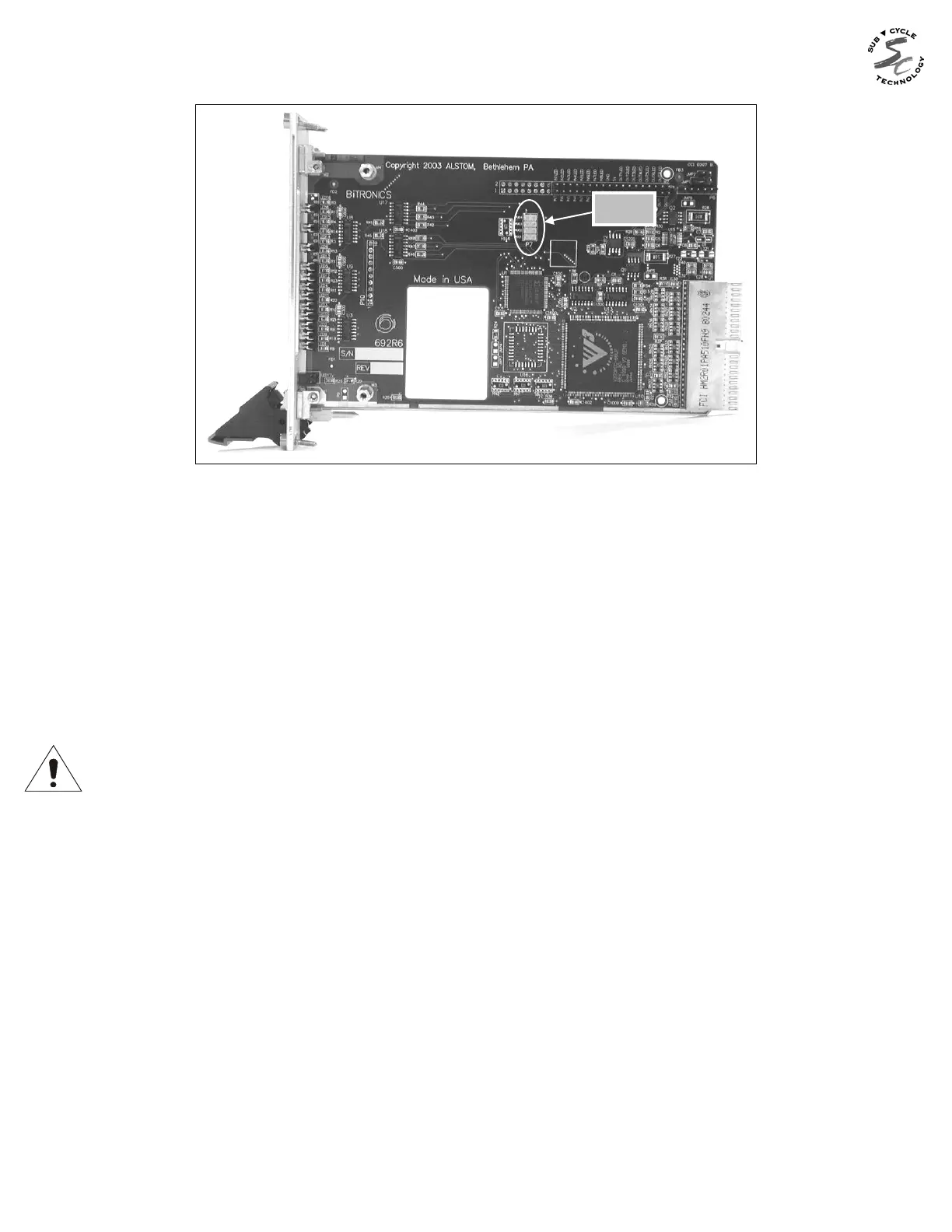
Figure 15 – P7 Jumper Location
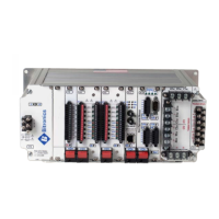
9.10.4 I/O Board (693) Jumper Settings
There are several jumpers for setting the input range and threshold on the I/O board and
for the normal state of the output relay contacts. The board and jumper locations are
shown in Figures 16 and 17. Range jumpers for Inputs 1-8 are located on PCB 693; inputs
9-16 (P31 only) are on PCB 716. The jumpers are red in color for high visibility. Refer to
the beginning of this section for the procedure to access the jumpers.
When the input jumper is installed, the input is in LOW RANGE mode. Removing the
jumper places the input in HIGH RANGE mode. THE FACTORY SETTING IS HIGH
RANGE (JUMPER IS PLACED IN THE STORAGE POSITION). REFER TO SECTION
9.8.
The relay outputs can be set for Normally Open (NO) or Normally Closed (NC) operation.
To enable Normally Open operation, which is the factory setting, place the jumper from "C"
(common) to "NO". To enable Normally Closed operation, place the jumper from "C" to
"NC".
The relay outputs can be disabled if desired by placing the jumper vertically, from the "NC"
to the "NO" contacts, or by removing the jumper entirely. This may be desirable if only the
inputs are going to be used on these terminals, and the user wishes to guarantee the
outputs do not operate (see figure 18).