ML0021 August 15, 2018
135 Copyright 2018 Bitronics, LLC
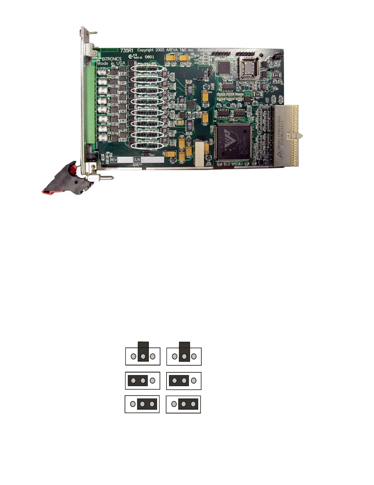
Input # 1
Input # 2
Input # 3
Input # 4
Input # 5
Input # 6
Input # 7
Input # 8
Figure 21 – P40 Input Type Jumper Locations
Each input has two configurable jumper blocks. One jumper block configures the
hardware (the actual input circuitry), the other jumper control block configures the firmware
and software driver (informs drivers of the status of the hardware selection). It is extremely
important that when reconfiguring any input, that both the hardware jumper setting and
firmware jumper setting for that input match (select the same input type).
Figure 21 (P40 Input Type Jumper Locations) shows the location of each input’s jumper
block pair. Each jumper block pair consists of two three pin headers and each header is
shipped with a shorting block. The position of the shorting block on the header determines
the input type configuration. Figure 22 (P40 Input Type Jumper Configuration)
demonstrates the shorting block positions for the three valid input configuration options.
0 - 10V
0 - 1mA
4 - 20 mA
Figure 22 – P40 Input Type Jumper Configuration