APPENDIX A IMU Technical Specifications
OEM7 SPAN Installation and Operation User Manual v4 143
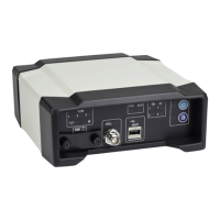
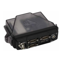
A.5.2 IMU-IGM Ports
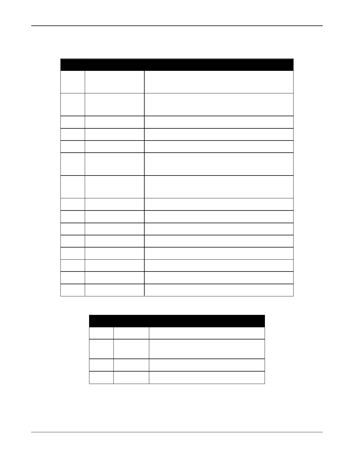
Pin # Label Description
1 MIC_TX/MIC_TX+
MODE2 high or open: MIC port transmit (RS-232)
MODE2 low: MIC port transmit positive (RS-422)
2 MIC_TX-
MODE2 high or open: No connection
MODE2 low: MIC port transmit negative (RS-422)
3 DGND Digital ground
4 V+ IMU-IGM power supply input, positive
5 V- IMU-IGM power supply input, negative
6 MIC_RX/MIC_RX+
MODE2 high or open: MIC port receiver (RS-232)
MODE2 low: MIC port receive positive (RS-422)
7 MIC_RX-
MODE2 high or open: No connection
MODE2 low: MIC port receive negative (RS-422)
8 DGND Digital ground
9 Reserved Reserved
10 Reserved Reserved
11 DGND Digital ground
12 Reserved Reserved
13 MODE2 Mode 2 input, controls MIC port standard
14 Reserved Reserved
15 Reserved Reserved
Table 49: IMU-IGM Main Port Pinout
Pin # Label Description
1 ODM_A+ Wheel sensor input A positive
2 ODM_B+
Wheel sensor input B positive
(No connection on IMU-IGM-S1)
3 Reserved Reserved
4 WS_VOUT Wheel sensor output voltage (12 VDC)
Table 50: IMU-IGM AUX Port Pinout


 To Next Page