Chapter 2 Connection
M
Novusun
Manual of NVBDH+/NVBDL+
cnc.prom.ua
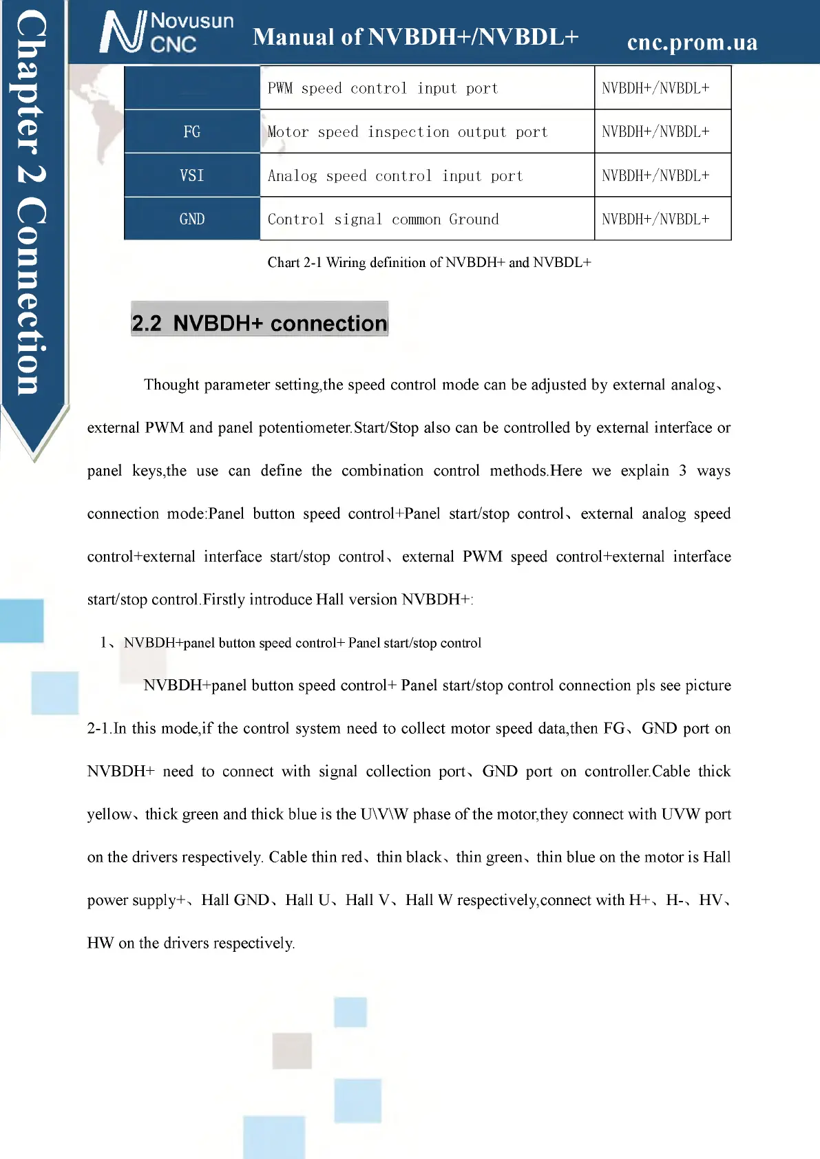
PWM
PWM speed control input port NVBDH+/NVBDL+
FG
Motor speed inspection output port NVBDH+/NVBDL+
VSI Analog speed control input port NVBDH+/NVBDL+
GND Control signal common Ground NVBDH+/NVBDL+
Chart 2-1 Wiring definition of NVBDH+ and NVBDL+
2.2 NVBDH+ connection
Thought parameter setting,the speed control mode can be adjusted by external analogx
external PWM and panel potentiometer.Start/Stop also can be controlled by external interface or
panel keys,the use can define the combination control methods.Here we explain 3 ways
connection mode:Panel button speed control+Panel start/stop controlx external analog speed
control+external interface start/stop controlx external PWM speed control+external interface
start/stop control.Firstly introduce Hall version NVBDH+:
1 x NVBDH+panel button speed control+ Panel start/stop control
NVBDH+panel button speed control+ Panel start/stop control connection pls see picture
2-1.In this mode,if the control system need to collect motor speed data,then FGx GND port on
NVBDH+ need to connect with signal collection portx GND port on controller.Cable thick
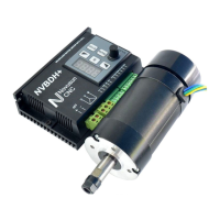
yellow x thick green and thick blue is the U\V\W phase of the motor,they connect with UVW port
on the drivers respectively. Cable thin redx thin black x thin greenx thin blue on the motor is Hall
power supply+x Hall GNDx Hall Ux Hall Vx Hall W respectively,connect with H+x H-x HV>
HW on the drivers respectively.