www.nvcnc.com
Chapter2 Connection
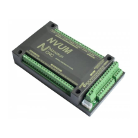
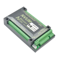
Manual of NVUM_SP
- 6 -
Chapter 2. Connection
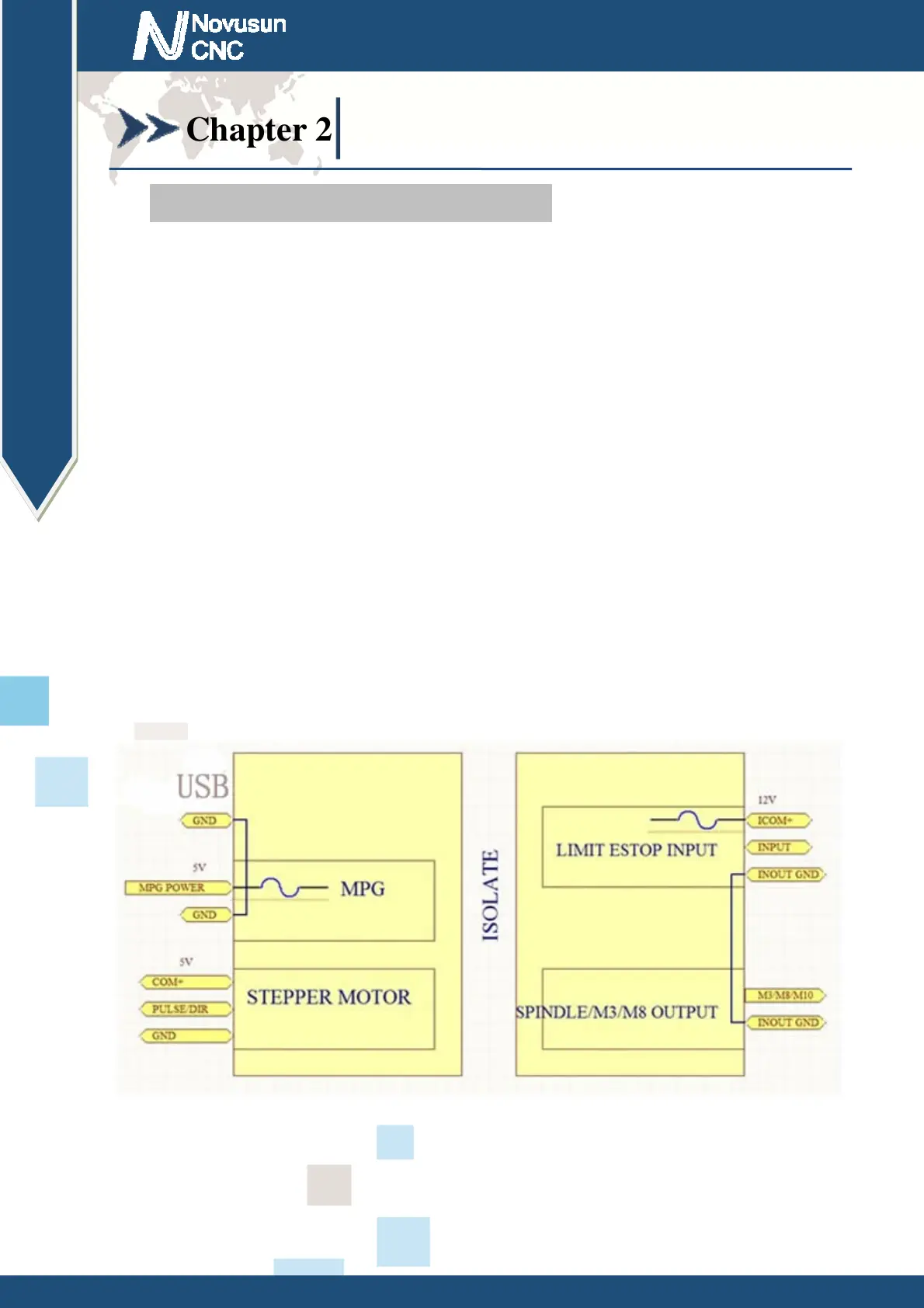
2.1 Device Power supply Solution
The power supply solution in the field of the Industrial automation is always very
complicated,there is a lot of the GND,now we descript the structure of the power supply as below:
The power supply structure as the Figure 2-1,main power supply input and MPG module and
stepper control output module are common GND,Limited and Estop input module and Spindle
speed adjust M3/M8/M1 module are common GND,between main power supply and output
module there are photoelectric isolation.The inputs of limited switch and Estop and so on are
Common anode, inside of the device, there is +12VDC as common+,no need to connect external
power supply. Based on the reference of output GND interface, output a 0-10V adjustable voltage
to adjust the the spindle speed,M3/M8/M10 digital output interface is open-GND. If connect an
external relay,need to output GND to refer to,and give the relay an external power supply.
Figure2-1. Power supply structure of NVUM_SP
 Loading...