www.nvcnc.com
Chapter2 Connection
Manual of NVUM_SP
- 7 -
2.2 Product connection define and method
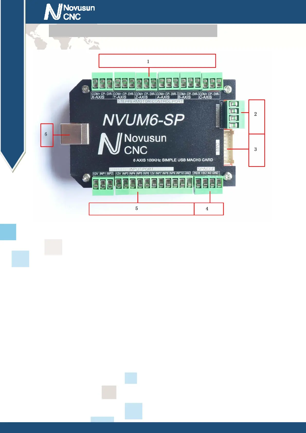
Figure2-2. Product wiring section and interface summary
As the Figure 2-2 showed,the connection of the controller includes USB connection
interface, MPG interface, Stepper/Servo control output interface, spindle control output interface,
Estop and limited switch and tool setting input interface and so on. Now we descript them in
details as below.
2.2.1 Stepper motor control interface
As Figure 2-2 showed,No.1 terminal block is 6 axis stepper driver control output interface,
from left to right,there are X,Y,Z,A,,B,C 6 axis output, it’s common anode,the cable connection for
each axis is COM+/CP-/DIR-, COM is common+ ,CP is Pulse-, DIR is direction-.Connection
showed as Figure 2-3.COM+ connect with the SP+ and DIR+.
 Loading...