Bottle Cap
lrrigation
Tube Needle
Tube Clamp
Tube Cap
Power Switch
Symbol Mark
Function OFF ON
6-1 Programming the micromotor operation
The control unit can memorize 10 sets of programs. Each program includes the following
functions which will be automatically performed when the appropriate program number is
selected.
Gear ratio of contra angle handpieces
Speed
Direction of rotation
Torque upper limit
Coolant solution flow
a Turn on the power by pushing the main switch toward [
-
].
Whenever the main power switch is turned ON, program
number 1 is always displayed.
s Select a program number by using either step a) or step b):
O a Press the [Program] key on the unit control panel
until the program number you require is displayed OR
O b Press the [Program] button on the foot control until the program number
you require is displayed.
d Selecting the gear ratio of the handpiece relevant to the program
Press the [Gear Ratio] key the gear ratio of the handpiece to be used is displayed.
f Setting the speed
Set the speed by pressing the [Speed] key.
-Each time this key is pressed the display changes to the next speed level. By pressing this key
for more than 1 second brings the speed quickly to the next level until the speed display
reaches its upper or lower limit.
-When the speed setting reaches the upper or the lower limit, an audible beep is heard and the
speed setting cannot be changed any further.
g Setting the torque upper limit
Set the torque upper limit by pressing the [Torque] key on the unit control panel.
-Each time this key is pressed the display changes to the next torque level. By pressing this key
for more than 1 second brings the torque quickly to the next level until the torque display
reaches its upper or lower limit.
-When the torque setting reaches the upper or the lower limit, an audible beep is heard and the
torque cannot be changed any further.
h Select the rate of coolant solution flow volume
Select the rate of the coolant solution flow volume by pressing the [Coolant Flow] key.
-The rate of coolant solution flow volume has 5 flow rate steps plus "no coolant flow".
j Memorize settings
After completing steps 1-6 press the [Memory] key for more than 1 second until a long
audible beep is heard. The long beep confirms that the programming is completed. If you hear a
short audible beep when the [Memory] key is first pressed please ignore this signal and
keep the [Memory] key depressed until a long beep is heard.
Repeat the above steps 1-7 to program any one of the 10 available programs.
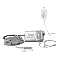
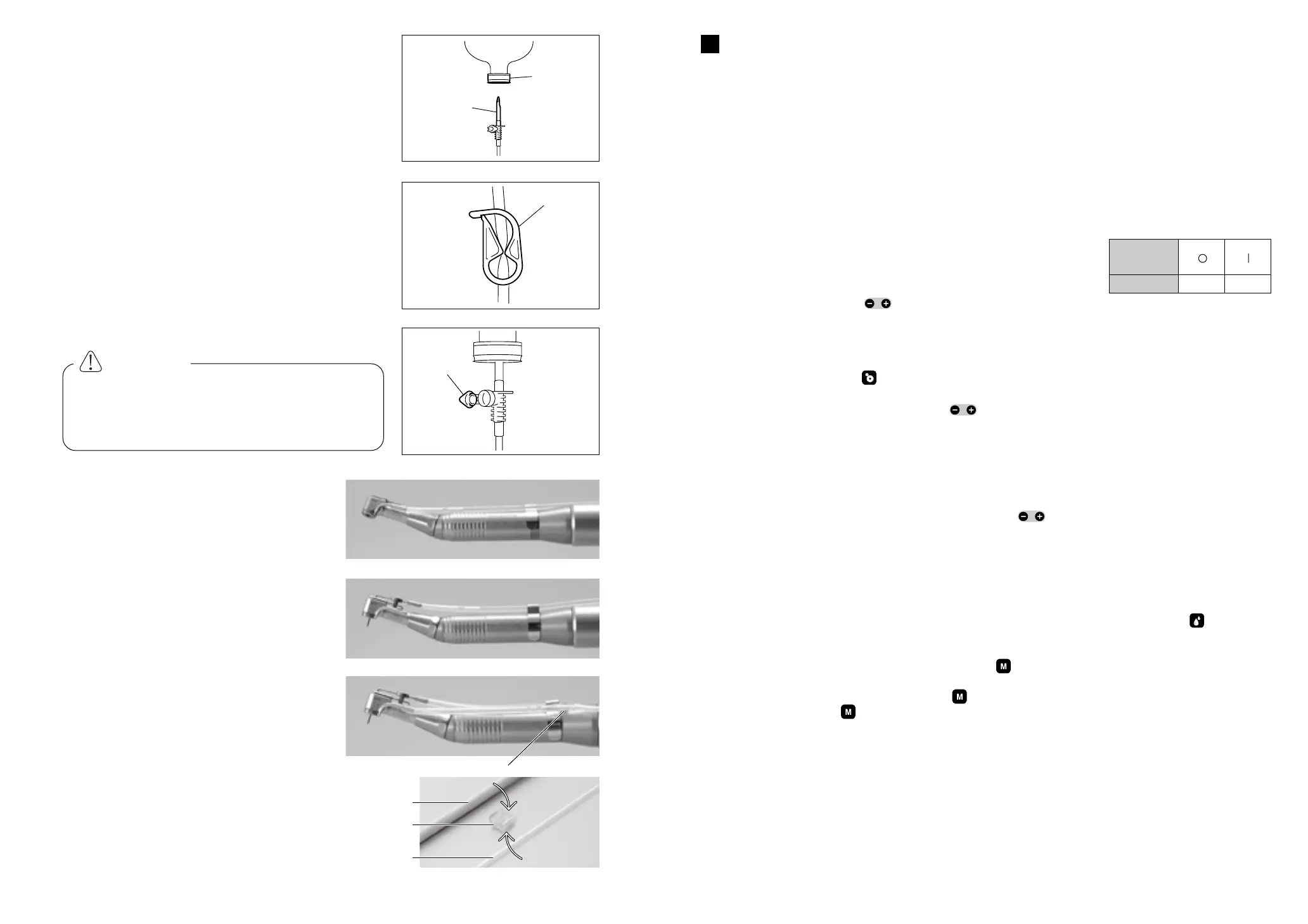
5-6 Insertion of the irrigation tube
a Place the coolant solution bottle on the hanger post
and insert the irrigation tube needle into the bottle
cap. (Fig.11)
s Close the tube clamp, between the irrigation tube
needle and the irrigation pump, as shown in Fig.12
d Open the tube cap to supply air into the bottle.
(Fig.13)
5-7 Mounting the internal spray nozzle
It is possible to connect water to the external
irrigation nozzle (Fig.14) and the internal
irrigation nozzle (Fig.15) simultaneously.
Simply connect the Y connector (Fig.16) onto
the main water supply tube at the rear of the
handpiece then connect the 2 water supply
tubes.
5-8 Attaching the tube holder
Use the tube holder to combine together the
motor cord and the irrigation tube. It is easier
to insert motor cord first and, next, the
irrigation tube.
Operation
6
oi
CAUTION
Do not operate the irrigation pump if the
tube is bent or the tube clamp is in the
closed position. This could cause the tube
to burst or slip out of the bottle.
Fig.11
Fig.12
Fig.13
Fig.14
Fig.15
Fig.16
Fig.17
Motor cord
Tube holder
Irrigation tube
Y-connector
PROGRAM
SPEED
TORQUE
 Loading...