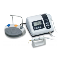
Description
Philips screwdriver
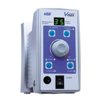
Speed Display
Motor ON/OFF LED
Motor ON/OFF Switch
Speed Control Knob
HAND LED
HAND/FOOT Selector Switch
FOOT LED
Output Connector
Auto Cruise LED
Auto Cruise Switch
FWD LED
FWD/REV Selector Switch
REV LED
Power Switch
Handpiece Holder
Foot Control (FC-40)
Motor Handpiece
Handpiece Stand
Foot Control Connector
AC Power Fuse Box
Power Cord
Installation
Adjusting Angles of Suspension Arm
Angles of A and B are freely adjustable. (Fig. 11) If adjusting the angles repeatedly,
the joint parts might become loose. Tighten the screws with Phillips screwdriver on both sides. (Fig. 12)
1. Connecting Motor Cord Plug
Insert the motor cord plug in Output Connector .(Fig.3)
2. Connecting Power Cord
Insert Power Cord plug in AC Power Fuse Box
at the back of the control unit, aligning the fuse box and plug. (Fig. 4)
3. Connecting Foot Control
Insert Foot Control plug in Foot Control Connector
at the back of the control unit. (Fig. 5)
4. Mounting Handpiece Holder
Mount Handpiece Holder at either side of the control unit.
Adjust the angle and tighten the screw. (Fig. 6)
*Handpiece Holder can be mounted at either side of the control unit.
5.
Assembling and Mounting Suspension Handpiece Cradle (Option)
Mount Handpiece Cradle
Mount the handpiece cradle and other parts at the end of the suspension
arm as shown in Fig. 7 and secure with the nut.
Mounting on Control Unit
Mount the suspension arm on either side of the Control Unit, on which
the handpiece holder is not attached, and secure with the screw. (Fig. 8)
Adjusting Length of Suspension Arm
Loosen the fastening ring of the suspension arm to extend the arm
and secure with screw. (Fig. 9)
Setting Motor Cord
Place the motor handpiece on the handpiece cradle on the work bench.
Take enough cord length for work, and lock the motor cord in the cord
clamps on the suspension arm. (Fig. 10)
Control
Unit
7
6
5
4
3
2
1
8
9
10
11
12
13
14
15
16
17
18
19
20
21
1
2
3
4
5
6
7
Fig.12Fig.11
Tighten Joint Section
of Arrow C on Fig.11
Cord Clamp
Fig.10
Fig. 7
Fig. 6
Fig. 5
Fig. 4
Fig. 3
Fig. 8
Fig. 9
Fastening Ring
Loosen
Tighten
Assembling of Hpc. Cradle
15
14
8
13
12
11
10
9
16
17
18
19
20
21
8
20
21
19
15
8
21
20
16
19
15
15
 Loading...