Fig.14
Fig.19
Joint Nut
No signal from Foot Control .
Fig.16
Protective Circuit
When the control unit is overloaded or the motor is to operate in spite of the chuck control lever or the bur lock ring is
in open position, the protective circuit functions to stop the motor and Speed Display shows error codes.
To reset the protective circuit,
・ At manual operation, press Motor ON/OFF Switch .
・ At foot control operation, release Foot Control .
3
Error Code
When the motor stops operation, Speed Display shows error codes, which instruct what is problem.
1
Refer to Troubleshooting for action taken when the error code shows.
Detection of overcurrent
Detection of overvoltage
Detection of discontinuity in
Speed Control Knob
Detection of discontinuity in
Foot Control
Overheating inside the control unit
Breaking circuit error
EEPROM abnormal
Rotor lock error Faulty PC Board.
Internal memory faulty.
・ Abnormal voltage in the starting or the shut-down circuit.
・ The starting or the shut-down circuit trouble.
Long-time use at excessive load built up heat inside the control unit.
・ Long-time use at excessive load (Overcurrent).
・ Short-circuited power cord.
・ Handpiece trouble.
・ Short-circuited motor winding.
・ Open collet chuck.
Faulty PC Board.
No signal from Speed Control Knob .
4
4
Fig.15
Fig.18
Fig.13
Handling Motor and Handpiece
1. Replacing Tool
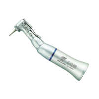
a.) Ring type handpiece
To unlock the collet chuck and remove the tool, turn the bur lock ring to OPEN
with a click. To tighten the collet chuck and mount the tool, turn the bur lock
ring to LOCK with a click. (Fig. 15)
b.) Lever type handpiece
To unlock the collet chuck and remove the tool, make a quarter turn of
the chuck control lever to OPEN. To tighten the collet chuck and mount
the tool, turn the chuck control lever back to LOCK. (Fig. 16)
2. Cleaning and Replacing Collet Chuck
Caution
Make sure that the chuck control lever or the bur lock ring is at lock position when starting the motor handpiece.
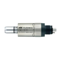
3. Connecting and Disconnecting Motor Cord and Motor
To remove the motor cord, loosen the joint nut at the back of the motor.
To connect, align the + marks of the motor and the joint nut. Insert the pins
completely and tighten the joint nut. (Fig. 19)
*If connecting inversely, the motor will run in the reverse direction.
OPEN
LOCK
OPEN
LOCK
Fig.17
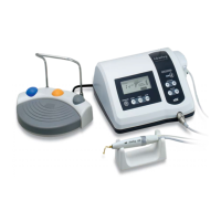
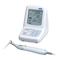
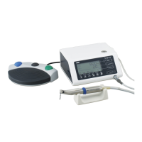
Operation Procedures
(1) Insert Power Cord plug into an outlet.
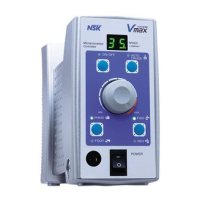
(2) Make sure that Speed Control Knob is set to the lowest position.
(3) Turn on Power Switch , and check if Speed display shows.
(4) Select either forward or reverse direction by FWD/REV Selector Switch . Every pressing alternates FWD and REV.
(5) Select either hand or foot operation by HAND/FOOT Selector Switch . Every pressing alternates HAND and FOOT.
Replacing AC Power Fuse
There is a fuse in AC Power Fuse Box . Push links at the either side of
the fuse case and remove to check.
If the fuse is blown, replace with a new fuse of same rating.
(AC120V: 3.15AH 125V) (AC230V: T800mAH 250V) (Fig. 14)
(1) Removal of Chuck
To remove the chuck, open the bur lock ring or the chuck control lever and
turn the chuck counterclockwise with the provided spanner wrench. (Fig. 17)
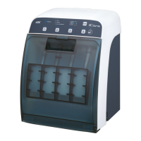
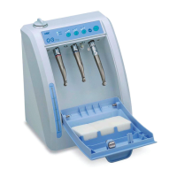
(2) Cleaning of Chuck
Remove and clean the chuck as frequently as possible in the ultrasonic
cleaner. Clean at least once a week.
(3) Insertion of Chuck
Thinly apply oil before insertion.
Open the bur lock ring or the chuck control lever, insert the dummy bur or
the bur in use into the chuck, and turn the chuck clockwise by hand until it
stops. Then, lock the bur lock ring or the chuck control lever, and the chuck
could hold the bur securely. (Fig. 18)
21
4
1
14
12
6
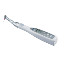
Operation-1
Manual Operation
After (1)-(4) operations above, go to the following procedures.
(5) Select hand operation by HAND/FOOT Selector Switch . (HAND LED lights.)
(6) To operate Motor Handpiece , press Motor ON/OFF Switch .
(Motor ON/OFF LED lights.)
(7) Adjust the rotation speed by turning Speed Control Knob .
(8) To stop Motor Handpiece , press Motor ON/OFF Switch .
(Motor ON/OFF LED stops lighting.)
Operation-2
Foot Control Operation
After (1)-(4) operations above, go to the following procedures.
(5) Select foot operation by HAND/FOOT Selector Switch . (FOOT LED lights.)
(6) To operate Motor Handpiece , apply pressure to Foot Control .
(7) Adjust the maximum speed by turning Speed Control Knob . The rotation speed can be adjusted by foot up to
the maximum speed, that is preset by Speed Control Knob . (Variable operation)
(8) To stop Motor Handpiece , stop applying pressure to Foot Control .
*Auto Cruise Mechanism
To operate Motor Handpiece at a constant speed below the maximum speed preset by Speed Control Knob ,
press Auto Cruise Switch when the motor handpiece rotates at the required speed. Auto Cruise LED lights
and the rotation speed would not change even if the foot Control is released. To cancel auto cruise operation,
press Auto Cruise Switch or Foot Control once again.
6
5
17
16
3
2
4
17
3
2
6
7
17
4
4
17
17
4
10
10
9
16
1
16
16
16
16
Loosen
Turn until snug
Caution
Neglecting to clean the chuck for a long time is very dangerous
because wax, gypsum, etc., accumulate in the chuck and the bur is
caught insecurely, causing runout.
Caution
Fuse is burned out when a short circuit occurs or when over-voltage
flows into the primary current source. If the cause is uncertain,
return the product to an authorized NSK's service shop for inspection.
molded + markings molded + markings
14
12
6
5
4
3
2
1
20
 Loading...