Lx Series Installation and Operation Instructions │Trinity Lx
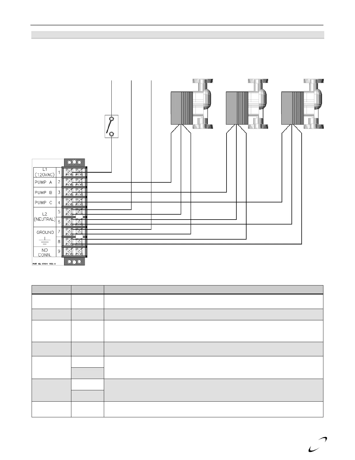
Figure 12-1(a) Line Voltage Field Wiring (Lx150-400)
Table 12-1(a) Line Voltage Field Connections (Lx150-400)
Location for connecting line voltage of the power supply. Note; most installation codes
require the installation of a service switch to break line voltage to the boiler.
120VAC output to the DHW circulator; powered during a demand for DHW.
120VAC output to the Boiler circulator; powered during all demands; DHW, local Central
Heat (CH1) and Lead-Lag Central Heat [CH2 (LL)]. This output is not used for all
plumbing configurations, see Section 10.0.
120VAC output to the Central Heating circulator; powered during a demand for local
Central Heat (CH1) or Lead-Lag Central Heat [CH2 (LL)].
Location for connecting neutral of the power supply and all circulators.
Location for connecting earth ground and for grounding all of the circulators.
This terminal is used only for factory wiring, do not add or remove wires from this
location.
SERVICE SWITCH
(field supplied)