Trinity Lx │Installation and Operation Instructions Lx Series
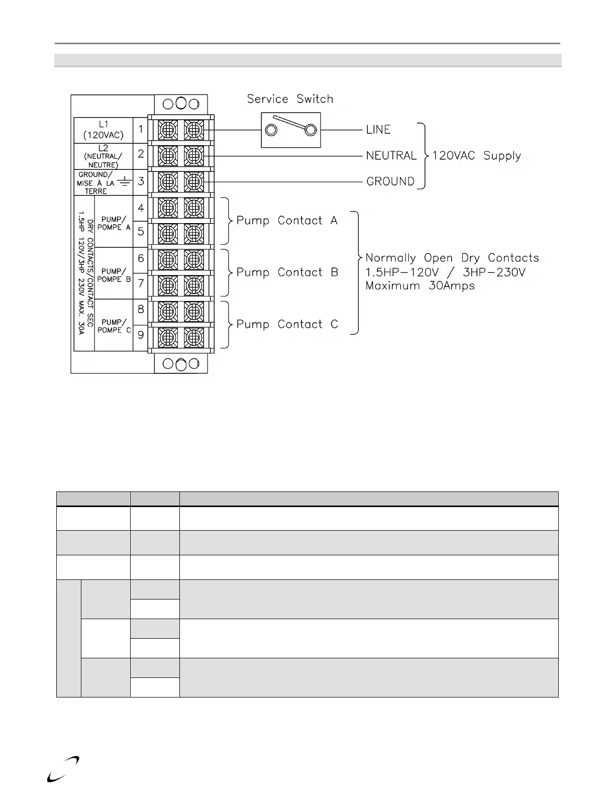
Figure 12-1(b) Line Voltage Wiring (Lx500-800)
Table 12-1(b) Line Voltage Field Connections (Lx500-800)
Location for connecting line voltage of the power supply. Note, most installation codes
require the installation of a service switch to break line voltage to the boiler.
Location for connecting neutral of the power supply.
Location for connecting earth ground.
Dry Contacts for DHW circulator; Coil A powered during a demand for DHW, closing
Pump A relay contacts.
Dry Contacts for Boiler circulator; Coil B powered during all demands; DHW, local
Central Heat (CH1) and Lead-Lag Central Heat [CH2 (LL)], closing Pump B relay
contacts. This output is not used for all plumbing configurations, see Section 2.0.
Dry Contacts for Central Heating circulator; Coil C powered during a demand for local
Central Heat (CH1) or Lead-Lag Central Heat [CH2 (LL)], closing Pump C relay contacts.